


Multi-Sensor Data Acquisition for Autonomous Vehicle Perception
Aleksandra Rodak, and Anna Niedzicka
Motor Transport Institute
April 7, 2026
As automated vehicles move toward SAE Levels 3–5, perception algorithms demand datasets that reflect real-world diversity—not idealized conditions. DARTS-PL addresses this challenge by delivering a high-resolution, fully synchronized, multi-sensor on-road dataset tailored to the infrastructure and climate of Central and Eastern Europe. Designed as an open, national resource, DARTS-PL bridges the gap between global benchmarks and local driving realities.
Introduction
The project, DARTS-PL, is designed as a national on-road scenario database dedicated to the development and testing of perception algorithms for automated vehicles. The project will provide high-resolution, synchronized, multi-sensor data under a free-to-use access license.
The DARTS-PL aims to develop a national database of test scenarios for autonomous vehicles (AVs) that account for road conditions specific to Poland.
Such a national on-road scenario database helps develop and test perception algorithms for automated vehicles. The project will provide high-resolution, synchronized, multi-sensor data under a free-to-use access license.
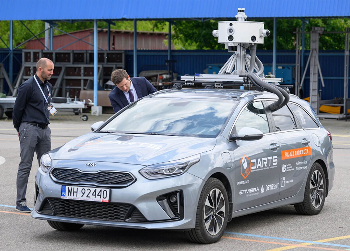
To collect the relevant data, we have equipped a vehicle with a sensor suite comprising 4 lidars, 7 cameras, 6 radars, an IMU-GPS-RTK module, and a thermal camera.
Multiple sensors are fully synchronized and calibrated inside DewesoftX data acquisition software that operates as a central data acquisition system.
The issue
Since its launch in 2014, SAE J3016™ Recommended Practice: Taxonomy and Definitions for Terms Related to Driving Automation Systems for On-Road Motor Vehicles, commonly referenced as the SAE Levels of Driving Automation™, has been the industry’s most-cited source for driving automation.
According to SAE J3016, the vehicle's Advanced Driver Assistance Systems (ADAS) levels 3–5 represent the transition from human-monitored driving to full vehicle autonomy:
Level 3 (Conditional Automation) allows the car to handle all driving tasks in specific conditions, with the human as a fallback.
Level 4 (High Automation) operates without human intervention in defined areas, while
Level 5 (Full Automation) requires no human driver under any conditions.
As the global automotive industry prepares for high levels of automation (SAE Levels 3-5), one of its challenges is the large-scale availability of diverse, representative, high-quality datasets for training and validation of perception algorithms. As the field is rapidly evolving, the total number of datasets is hard to determine.
In 2024, Liu et al. [1] identified 265 published autonomous driving datasets. His study reveals a notable characteristic of current autonomous driving datasets. Most of them rely heavily on camera-based sensing, particularly monocular and stereo cameras (see Figure 1).
While these sensors are cost-effective and widely deployable, they are inherently susceptible to environmental disturbances, including poor lighting, glare, shadows, rain, fog, and occlusions. In this respect, they exhibit limitations similar to those of human vision, which adverse weather or challenging lighting conditions can impair.
Although complementary sensors such as lidar and radar are increasingly incorporated to enhance robustness, camera-dominant datasets reflect a continued dependence on vision-based perception systems that remain vulnerable to the same types of uncertainties and ambiguities that affect the human eye.

![Sensor distribution in autonomous driving datasets, based on [1].](https://www.datocms-assets.com/53444/1775574108-sensor-distribution-in-autonomous-driving-datasets.png?auto=format&fit=max&w=1024 "Sensor distribution in autonomous driving datasets, based on [1].")
To address these limitations, researchers are developing a range of technical and methodological solutions. One of the most important is multi-sensor fusion, which combines cameras with complementary technologies such as lidar and radar. Unlike vision sensors, radar is more resilient in adverse weather, while lidar delivers precise geometric depth information independent of ambient lighting.
Fusing heterogeneous sensor data at the feature, intermediate, or decision level allows perception systems to compensate for the weaknesses of individual modalities and achieve greater robustness, reliability, and redundancy.
Surveys and review studies consistently identify the need for larger and more diverse datasets as a foundation for progress in autonomous driving research [2]. Dataset diversification is particularly important. Expanding coverage across weather conditions, geographic regions, traffic situations, and rare edge cases improves the real-world performance of automated driving systems.
According to Liu et al. [1], however, most existing datasets are concentrated in high-income regions. The United States represents 21 percent of datasets, while Germany and the rest of Europe each account for 12.6 percent. China follows with 8.4 percent, and countries such as Canada, Korea, the UK, Japan, and Singapore make up only small shares of 1 to 4 percent.
This imbalance means that existing datasets may not adequately represent the infrastructure, driving behavior, and climatic conditions typical of Central and Eastern Europe. Unique road geometry, local signage, and weather conditions such as heavy snow, rain, and fog can all present challenges for autonomous vehicle sensors.
DARTS-PL dataset – Polish testing scenarios
Given the underrepresentation of Central European driving conditions, the Polish National Centre for Research and Development funded the DARTS-PL project under the GOSPOSTRATEG VIII program (grant No. GOSPOSTRATEG-VIII/0001/2022).
A consortium of leading Polish research and academic institutions conducts the project:
Motor Transport Institute (ITS): responsible for defining the scenario requirements and coordinating the data acquisition process.
Warsaw University of Technology (PW): performing advanced data processing, sensor fusion, and annotation process.
The DARTS-PL dataset addresses the lack of high-resolution, multi-sensor datasets recorded under natural driving conditions in Poland. There is a need for AV-oriented data that is synchronized and covers not only common driving scenarios but also "edge cases", such as zones with high accident rates, on-road agricultural machines, and driving under low-visibility conditions.
Existing databases often suffer from "geographical bias" because they are recorded primarily in North America or Western Europe. This bias leads to gaps in algorithmic training for:
Infrastructure Variability: differences in road markings, infrastructure, road classes, and integration solutions.
Environmental Extremes: Sensor performance degradation during Central European winters (snow cover, salt spray), heavy rain, mists, etc.
Vulnerable Road Users (VRUs): Interactions with diverse participants, including cyclists and animals, which require high-fidelity 3D annotation.
Without localized data, AV systems deployed in Poland may fail to recognize specific hazards, leading to a "perception gap" that hinders domestic innovation and safety.
The DARTS-PL project establishes a national on-road scenario database. The core strategy involves recording more than 100 distinct road segments, each captured at least 8 times under varying conditions (day/night, four seasons), also covering edge environmental cases such as heavy rain, slush on the road, markings covered by snow or leaves, and many others.
The DARTS-PL project is following several principles to deploy an adequate solution:
Synchronization: sensors are hardware-triggered and time-stamped.
Open Access: Providing the data under a non-profit, free-to-use license for both commercial and academic applications.
Standardization: Data is in open formats for seamless integration into simulation environments.
Stakeholders
Researchers at the Motor Transport Institute developed the functional and non-functional requirements for the measuring set. Envibra sp. z o.o. was the contractor responsible for DARTS-PL data acquisition platform development. The company had support from the engineers of:
Dewesoft - software updates, cameras, localization,
b-plus GmbH - main computing device, general time stamps, synchronization,
SEARCH - Safety Engineering Research - lidar and radar integration, including plugin development.
The team collaboratively resolved all problems encountered during the development of the measurement set. Exchanging countless messages and encountering problems that the component manufacturers themselves were unaware of. This project was no ordinary order, but a full-scale R&D project.
Requirements and potential issues
Developing a measurement system that met the customer’s requirements was a significant challenge in itself. The contract covered the complete delivery, including installation, configuration, commissioning, and user training for a software-integrated, multi-sensor measurement kit capable of 360-degree mapping and recording of the vehicle’s surroundings.
DARTS-PL wanted to record scenarios (drives) focused on specific infrastructure solutions or road situations that could be problematic for automated driving systems, such as poor weather conditions, unclear signage, and vulnerable road users within the roadway.
A single scenario, approximately 20 seconds long, was to be extracted from a single recording session of approximately 10 minutes. The measurement system should accurately record all parameters up to a maximum vehicle speed of 130 km/h.
DARTS-PL proposed the sensor layout, while Envibra and Dewesoft had to integrate the measurement system with the vehicle. The measurement set was to be mounted in the roof section in a "box" form, allowing for easy removal.
The parts of the measurement system not contained within the box or inside the bodywork were to be equipped with adhesive mounting pads to allow easy installation anywhere in the vehicle. Cable connections must enable the set to operate smoothly with closed doors and windows, preventing water and cold from entering the vehicle interior during measurements.
All data recorded by the measurement system, including images captured by the cameras, must be synchronized with the central clock. The ambient temperature range for proper operation of the measurement system was -10°C to +40°C, and for storage, -20°C to +40°C. The system should function properly under various weather conditions, including heavy rain or strong winds, for approximately 6 hours on the measurement day. It should also be resistant to dust and other small airborne particles.
Sensor eequirements
Cameras
Color video recording at a resolution of no less than 1920 pixels by 1080 pixels at a minimum of 25 frames per second.
HDR technology with an auto-exposure function, with the ability to independently turn off both functions.
Raw (uncompressed) images.
Setting and locking the focus and white balance at a given position.
Covering of at least 20 degrees from the horizon with the vehicle in a horizontal position.;
Global shutter technology.
Utilize sensors (matrices) no smaller than 1/2".
Image recording parameters, particularly exposure (shutter speed and gain), should be recorded for each frame.
Lidar - medium range
At least 128 laser beams.
Minimum frequency of 20 Hz (the frequency should be configurable from 10 revolutions per second).
Range of at least 200 m, a vertical range of at least 30°, and a horizontal range of 360 degrees (rotational).
Accuracy of 3 cm or better and a horizontal scanning resolution of 0,25° or better.
Lidar - long range
Capture the area centrally in front of the vehicle, and place it on its axis.
Minimum frequency of 20 Hz (recommended that the frequency be configurable).
Measurement range of at least 200 m, a horizontal range of at least 20°, and a vertical range of at least 15°.
Accuracy of 3,5 cm or better and a horizontal scanning resolution of 0,26° or better.
Lidar - short range
Suggested horizontal range is 120° or greater, with a suggested minimum elevation angle of -75° to +15°.
Minimum frequency of 20 Hz (configurable frequency recommended).
Minimum of 64 laser beams.
Measurement range of at least 30 m.
Radars – corners
Range of 1-30 m.
Minimum frequency of 13 Hz.
Horizontal range of at least 75° and a vertical range of at least 15°.
Radars – front & back
Range at least 80 m.
Minimum frequency of 13 Hz.
Horizontal range of at least 60° and a vertical range of at least 15°.
Inertial navigation systems (INS, IMU) and RTK
Navigation accuracy using the RTK method is no worse than 10 cm horizontally.
Support heading measurement with a dynamic accuracy of at least 0,1°.
Measure speed with an accuracy of at least 0,05 m/s up to at least 200 km/h.
GPS sampling rate of at least 100 Hz.
Data recorded by IMU:
Linear acceleration vector (x, y, z) in the IMU frame in m/s2.
Angular velocity in rad/s around the x, y, and z axes, respectively, in the IMU coordinate frame.
Vehicle position: acceleration vector in the EGO vehicle frame in m/s2, rotation (orientation) vector in the EGO vehicle frame.
Thermal imaging camera
Resolution of at least 640x480 pixels.
Minimum of 25 frames per second.
Thermal sensitivity of 50 mK or less.
Sensor power supply
Capacity to independently power a functioning measurement system for at least 4 hours.
The power supply must not be permanently mounted in the vehicle to prevent removal.
Charging from mains.
Must not be powered directly from the vehicle's electrical system, but may be charged from a 12V cigarette lighter socket (with appropriate restrictions).
If the devices in the measurement system require AC power, they must be pure-sine-wave devices.
Data acquisition and measurement equipment
Envibra chose to equip the research vehicle with 19 sensors. The number of sensors is still growing and integrated via the DewesoftX software. They selected the following components to meet our requirements (in some cases exceeding the requirements, e.g., see short-range lidar – OS Dome).
Data logger
b-Plus Brick2 data logger with BMC module and BMC ETH6000 card.
Inertial navigation
Dewesoft NAVION i2 inertial navigation system (INS) with a sampling rate of 100 Hz for real-time positioning data. The Navion i2 unit embeds a GNSS sensor with an accuracy of less than 10 cm using a RTK correction service via RTK base-stations.
Imaging
Seven high-speed Dewesoft DS-CAM-640c cameras are used where six are covering horizontal 360 ° FoV (Field of View) and one central camera with a different lens dedicated to far-ahead vision.
Camera specs:
Imaging Sensor: Sony IMX252 CMOS.
Maximum resolution of 2048 x 1536 px with a frame rate of 200 fps.
Features a global shutter with exposure times ranging from 1 µsec to 60 seconds.
Dynamic Range: 71dB.
LIDAR sensors
Four LIDAR sensors are installed:
Ouster OS1 – placed centrally in the vehicle axis, 360 ° FoV
360° horizontal field of view and a 45° vertical field of view.
Vertical resolution of 128 beams
Horizontal scanning resolution is 0.25°, with a precision of ±0.1°.
Maximum operational range of 200 m.
Frequency set at 20 Hz.
Ouster OS2 – placed centrally in the vehicle axis, long-range application,
360° horizontal field of view and a 22.5° vertical field of view.
Vertical resolution of 128 beams.
Maximum operational range of 350 m.
Frequency is 20 Hz, configurable to 10 Hz.
Two Ouster Dome – placed diagonally at the side edges of the vehicle,
180° vertical field of view.
Vertical resolution of 128 beams.
Horizontal scanning resolution is 0.7°.
Maximum operational range of 45 m.
Radar sensors
Six radar sensors are installed:
Two DRVEGRD 152 – recording the space in front of and behind the vehicle at a long distance
Operates within the 76–77 GHz band.
Sampling rate is 16,6 Hz.
Range from a minimum of 0,9 m to a maximum of 200 m.
Provides a 100° horizontal angle and a 20° vertical angle.
Tracking speeds ranging from -400 km/h to +200 km/h.
Distance accuracy rated at <0.45 m.
Four DRVEGRD 169 – placed in the corners of the vehicle
Operates within the 77–81 GHz band.
The sampling rate is 16,6 Hz.
Operational from a minimum of 0.6 m to a maximum of 56 m.
Provides a 130° horizontal angle and a 15° vertical angle.
Tracking speeds ranging from -340 km/h to +140 km/h.
Distance accuracy rated at <0.3 m.


Additionally, the system contains a REDARC-based power and battery management system.
Issues and solutions
We met the hardware requirements by selecting components compatible with the DewesoftX platform. The main challenge was integrating lidar and radar sensors, which had not previously been used with the software.
To solve this, engineers from Search, Dewesoft, and Envibra jointly developed a custom plug-in that enabled direct sensor control within DewesoftX, eliminating the need to rely on Ouster Studio, the sensors’ native software. This took significant time due to limited documentation and the complexity of coordinating with teams responsible for individual DewesoftX functions.
Below is an overview of the main challenges and how they were addressed.
Issue 1: Extracting short scenarios from longer recordings
Solved. DewesoftX already supports cutting approximately 20-second scenarios from longer recording sessions of around 10 minutes.
Issue 2: Integrating the measurement system into the vehicle
Solved. Wherever possible, the system was installed without modifying the vehicle’s structure. For example, the radars were mounted behind the bumpers without affecting the vehicle’s exterior. The installed sensors also do not interfere with the vehicle’s driver assistance systems.
Issue 3: Mounting the system on the roof in a removable enclosure
Solved. We designed a dedicated dome mounted on a frame, which was then attached to the roof rack using the vehicle’s existing roof rails. This made the entire setup removable.
Issue 4: Mounting external components with adhesive pads
Solved. Components located outside the dome or vehicle body were fitted using adhesive mounting solutions. This approach is used, for example, for the navigation antennas.
Issue 5: Synchronizing all recorded data to a central clock
Solved. All components share the same time reference. We implemented a master-slave architecture, with the first camera acting as the master and the remaining components as slaves. Where possible, synchronization was handled via the PTP communication protocol.
Issue 6: Routing cables while keeping doors and windows closed
Solved. We designed a dedicated sleeve to protect and route the cables. The left rear door window was removed and replaced with a plexiglass panel featuring an opening for the cable pipe. The entire assembly was sealed, and enough slack was left in the cables to allow the door to open easily. As a result, that window is no longer functional.
Issue 7: Operating in temperatures from -10°C to +40°C
Partially solved. The 40 W heater installed inside the dome did not provide enough heat to maintain proper operating temperature in very cold conditions. In practice, this means the system cannot be used below -5°C. Storage performance remains unverified, although the vehicle is kept in a garage.
Issue 8: Recording accurately at speeds up to 130 km/h
Solved. The roof rack is certified for speeds of up to 130 km/h, which meets the requirement. However, for safety reasons, the vehicle is not driven faster than 110 km/h during operation.
Issue 9: Operating reliably in harsh weather for up to six hours
Solved. We used automotive-grade sensors, lidars, and radars designed for outdoor use in demanding weather conditions. The cameras were housed inside a sealed metal dome to protect them from moisture and dust, while the window sleeve shielded the cable routing from wind and other environmental factors.
Additional issues
Vehicle weight – after all assemblies, the car turned out to be too heavy. It is therefore now registered for 3 passengers instead of 5.
Camera lenses fogging – due to the temperature difference between the inside and outside of the dome, the camera lens holes fogged up. We had to place a moisture absorber in the dome.
DewesoftX time switch – when the source of time is changing from GPS to internal Brick2 oscillator, then the internal DewesoftX time switches from UTC to TAI;
HDR in cameras – despite the information in the technical specifications, cameras did not support HDR/12-bit. We could not resolve the issue.
The thermal camera is not sending timestamps and doesn’t support synchronization protocols – we may only synchronize it externally, and the synchronization is unstable.
Camera white balance settings in some conditions (night, low light) proved to spontaneously change even when we set the “Automatic white balance” option to “Off”. The issue occurred only when starting cameras in very low light conditions, and it affected only a single camera in the system (not always the same camera, and not all cameras at once). Requires further investigation.
Signal losses – while leaving areas without GSM connection (i.e., in tunnels), RTK is not always able to restore GSM communication itself and requires manual reset;
In low-light conditions, cameras automatically adjust exposure, increasing the exposure time. Previously, we incorrectly set the maximum exposure time to 1s/frame rate, which left insufficient time to complete one frame before starting the next. This error caused all cameras to lose synchronization. We resolved the issue by reducing the maximum exposure time by 100 microseconds.
Brick2 is not using NAVION i2 as a time source – after more than 1.5 months of testing and development, we needed to change the concept. Now Brick2 uses its own GPS to set the system's master time, with NAVION i2 working as a slave. Due to several other issues, we are now working with DS-IMU2.
Sporadic synchronization issues cause sub-second losses of lidar data, despite it being received and recorded for preview purposes; we haven’t resolved the issue yet.
Examples of sensor recordings
The DARTS-PL project is going to deliver a complex solution for developing and testing automated vehicles' perception algorithms:
Raw and Annotated Data: A massive repository of multi-modal driving data. At the end of the project (05/2027), there will be at least 840 scenarios from more than 100 chosen infrastructure segments.
Web Portal: A filtering and download service for specific scenario types (e.g., "Night + Pedestrian").
Auto-Annotation Software: Proprietary tools for object tracking and automated labelling to reduce manual labor in further database development.
In the project, we are using DewesoftX for scenario capture and data export. The software helps to generate data in accordance with project-specific rules. Below, we present several sample scenes visualized in DewesoftX software:


 in Warsaw, Poland.")
 in Warsaw, Poland.")


Conclusion
DARTS-PL, providing a high-resolution, synchronized, and "Poland-specific" dataset, bridges the gap between theoretical code and real-world road conditions. The open-access nature of the database ensures that it will serve as the foundational infrastructure for Polish and European AV perception testing for years to come, fostering innovation while ensuring the highest safety standards.
Now the project is in the data acquisition phase, and the first annotation processes are starting. We plan to make the first data available in the third quarter of 2026, and the full database will be ready in the first half of 2027.
Bibliography
Liu M, Yurtsever E, Fossaert J, et al. A survey on autonomous driving datasets: statistics, annotation quality, and a future outlook. IEEE Trans Intell Veh. 2024;9(11):7138-7164. doi:10.1109/TIV.2024.3394735
Hossain M, Islam MZ, Islam MS, et al. A comprehensive review on traffic datasets and simulators for autonomous vehicles. arXiv. Preprint posted online December 18, 2024. doi:10.48550/arXiv.2412.14207