


Virtual Sensor Validation with Synchronized Vehicle Measurement Data
Dr. Daniel Dilmetz, Global and Martin Zeller
COMPREDICT
May 14, 2026
Virtual Sensors can provide scalable insight and reduce the need for physical hardware, but their performance depends on the quality of the data behind them.
COMPREDICT uses Dewesoft technology to combine high-fidelity measurement, precise synchronization, and real-time demonstration in one vehicle platform. The same demo vehicle serves two purposes: it provides reliable reference data for Virtual Sensor validation and gives customers a live, practical demonstration of Virtual Sensor performance.
With Dewesoft as the measurement backbone, COMPREDICT can connect engineering-grade validation with a clear path toward scalable deployment.
Introduction
Virtual Sensors are increasingly central to modern automotive engineering. Instead of relying exclusively on physical sensors, Virtual Sensors compute critical quantities. These include:
temperatures,
forces,
torques, and
internal states
from signals already available in the vehicle.
These capabilities enable scalable functionality, reduce hardware complexity, and open new pathways for series deployment, fleet learning, and customer services.
At COMPREDICT virtual sensors are developed, calibrated, validated, and prepared for series deployment based on real vehicle data. The credibility of Virtual Sensors depends less on model sophistication than on the quality, synchronization, and traceability of the complete data pipeline—from vehicle bus inputs, to high‑quality ground‑truth reference measurements, to real‑time execution and verification.
COMPREDICT’s fully instrumented demo vehicle is used both as an engineering‑grade validation platform and as a customer‑facing demonstration vehicle. The challenge addressed is not only the acquisition of high‑quality reference data for Virtual Sensor calibration, but also the operation of a robust, repeatable live in-vehicle demonstration that convinces customers under real-world driving conditions.
Dewesoft OBSIDIAN, a rugged data logger and embedded data acquisition system, together with DewesoftX software, provides the measurement backbone for both use cases. The same platform supports high-bandwidth engineering measurements and standalone demo operation while maintaining signal quality, precise synchronization, and efficient workflows.
Virtual sensors definition and application areas
A Virtual Sensor is a software-based estimate of a physical quantity that dedicated hardware sensors in the system do not measure directly.
Instead of relying on additional instrumentation, a Virtual Sensor reconstructs the target quantity from signals that are already available—typically operational signals for core system functionality.
By combining these inputs with physical knowledge, data-driven models, or hybrid approaches, Virtual Sensors provide access to quantities that would otherwise require costly, complex, or impractical hardware instrumentation.


From an engineering perspective, a Virtual Sensor is defined by three closely connected elements:
Available input signals: Operational signals already present in the system, such as vehicle bus data or other measured values.
A calculation model: A physics-based, data-driven, or hybrid model that maps those inputs to the target physical quantity.
A reference basis: High-quality reference data used to calibrate and validate the Virtual Sensor.
Once validated, the Virtual Sensor can operate wherever the required input signals are available, even if no physical sensor exists for the target quantity. This makes Virtual Sensors scalable across platforms, vehicle variants, and deployment environments.
The value of a Virtual Sensor depends on why a quantity needs to be estimated and how the result will be used.
In some cases, Virtual Sensors give series-production systems R&D-level insight by making otherwise hidden quantities visible. In others, they replace physical sensors while preserving functionality and reducing cost. They can also support lifecycle services by estimating the condition, usage, or wear of vehicle components over time.
These use cases define the three application areas covered in the following sections: new SDV capabilities, hardware replacement, and after-sales solutions.
We have organized our Virtual Sensor portfolio into three application categories that reflect where this technology creates the most value today.
These categories address key challenges in the automotive industry: increasing system complexity, pressure to reduce cost and scale solutions across platforms, and the need to generate more value from vehicles throughout their lifecycle.
Many of these applications can also be adapted for dual-use scenarios and for other domains, including smart manufacturing and defense.

New SDV capabilities – turning series vehicles into R&D‑grade measurement systems
In Software-Defined Vehicle programs, Virtual Sensors bring R&D-level insight into series-production vehicles.
During prototype testing, engineers can measure quantities such as forces, torques, and internal loads using dedicated instrumentation. In series vehicles, those physical sensors are usually not available. Virtual Sensors reconstruct these quantities from standard in-vehicle signals, giving OEMs fleet-scale visibility into real customer usage and helping them identify where real-world behavior differs from design assumptions.
Typical examples include:
Wheel forces: Provide wheel-force-transducer-equivalent insight into real load spectra and durability-relevant usage.
Vehicle mass: Adds important context for braking, energy consumption, and vehicle dynamics under different payload conditions.
Damper forces, tie-rod forces, and driveshaft torque: Support chassis and driveline validation at scale, especially in electrified vehicles with fast-changing, high-torque dynamics.
Hardware replacement – preserving functionality while enabling cost and scalability
This category focuses on replacing physical sensors with software-based estimates while keeping the same functionality.
Physical sensors add more than component cost. They also require wiring, ECU interfaces, diagnostics, packaging space, and long-term maintenance. Virtual Sensors move this functionality from hardware to software, making it easier to scale across vehicle platforms and variants.
Typical applications include:
Headlight leveling without ride-height sensors.
E-motor temperature estimation for thermal protection.
Brake temperature awareness without thermocouples.
Tire pressure and tire temperature estimation without dedicated hardware.
Suspension displacement reconstruction without displacement sensors.
The same principle is also relevant in smart manufacturing and defense systems, where reducing hardware dependency can improve robustness, simplify maintenance, and increase system reliability.
After-sales and services – enabling data‑driven lifecycle value
The third category focuses on creating value after the vehicle has been delivered.
Virtual Sensors enable maintenance strategies based on real condition and usage, rather than fixed mileage intervals. By estimating brake wear and tire wear, they can support predictive service planning, improve safety, and help reduce the total cost of ownership.
Similar approaches are also used in defense and industrial systems, where condition-based monitoring supports predictive maintenance, higher availability, and mission readiness.
Virtual Sensor Development Requirements and Core Technology
Virtual Sensors map available operational signals to unmeasured physical quantities using physics‑based, data‑driven, or hybrid models. Independent of the modeling approach, successful deployment relies on input fidelity, reference quality, synchronization, and repeatable workflows.
Signal domain 1: operational signals available in the vehicle
Operational signals are signals that are already available in the vehicle because they support core functions.
Typical examples include wheel speed, steering angle, brake actuator position, and engine or e-motor speed. Since these signals are already present in series-production vehicles, they provide a scalable input layer for Virtual Sensors without requiring additional hardware.
Signal domain 2: reference Information for calibration and validation
Reference information provides the ground truth used to calibrate and validate a Virtual Sensor. It can come from several sources.
In test or demo vehicles, reference data often comes from additional high-quality sensors. Examples include wheel force transducers or strain-based load measurements. These sensors provide a reliable truth signal that the Virtual Sensor is trained or validated to reproduce.
Reference data can also come from existing sensors that may later be replaced. In this case, the current sensor signal is used as the benchmark, helping preserve the same functionality while reducing hardware and integration costs. Common examples include TPMS sensors and ride-height sensors used for headlight leveling.
For wear-related applications, such as tire wear or brake wear, the reference may come from dedicated measurement campaigns. These structured wear measurements provide ground-truth labels for automated model calibration. Once validated, the model can operate in the field using only standard vehicle inputs.
Virtual sensor implementation patterns: in‑vehicle, cloud, hybrid
Virtual Sensors can run in different environments, depending on the use case.
In-vehicle execution supports real-time functions and live demonstrations. It provides immediate feedback and gives customers visible proof of how the Virtual Sensor performs under real driving conditions.
Cloud execution supports fleet learning, batch validation, and scalable iteration across large datasets. This makes it useful for improving models over time and validating performance across many vehicles or test cases.
Hybrid execution combines both approaches. It is especially useful when working with legacy ECU limitations, safety-critical release processes, or limited on-vehicle computing power, while still allowing continuous model improvement.
Demo vehicle measurement architecture and why we chose Dewesoft
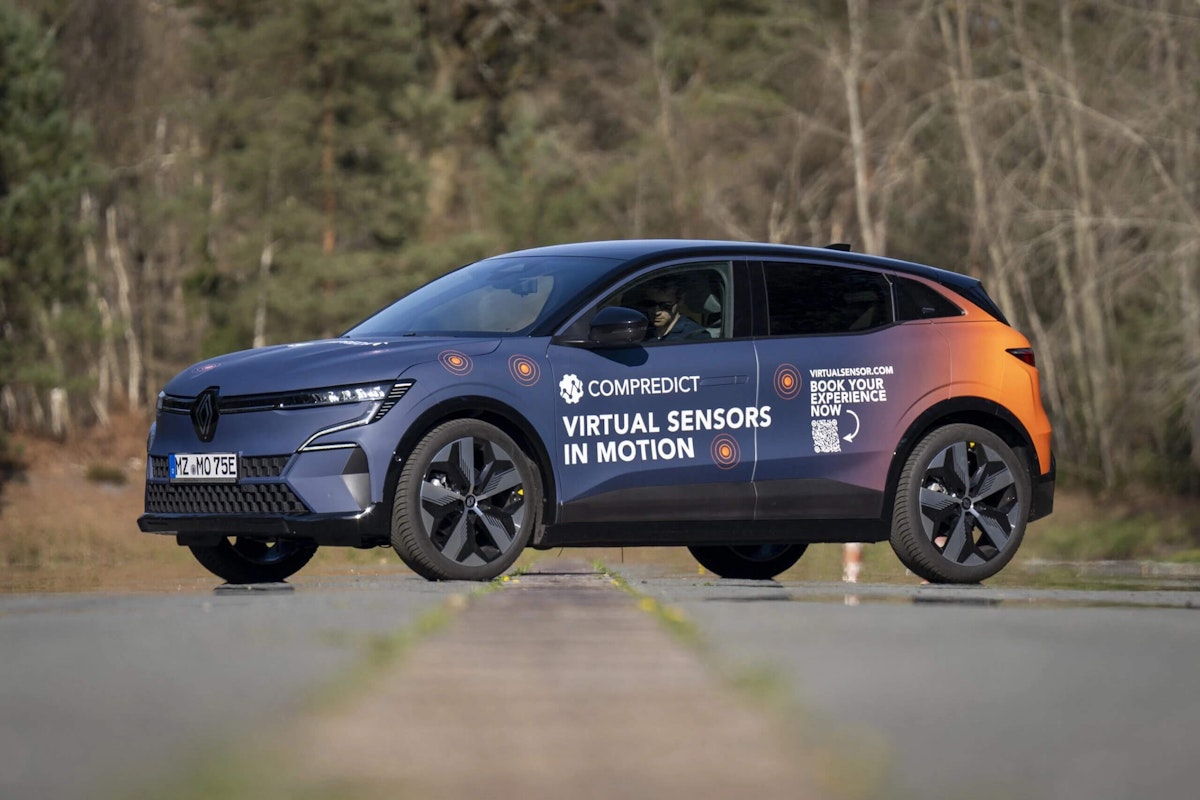
The main focus of the collaboration between COMPREDICT and Dewesoft is the COMPREDICT demo vehicle, known internally as the COMPREDICTOR.
The COMPREDICTOR is a Renault Megane E-Tech used for the joint development, validation, and demonstration of Virtual Sensors. It was designed to serve two purposes in one vehicle:
Engineering validation: The vehicle acts as a measurement platform for collecting high-quality, traceable reference data.
Customer demonstration: The same vehicle is used to show Virtual Sensor performance live, under real driving conditions.
For COMPREDICT, these two roles are closely connected. Virtual Sensors must be developed and validated against accurate, synchronized reference measurements. At the same time, customers need to experience the results in a real vehicle, in a way that is robust, transparent, and easy to understand.
The COMPREDICTOR brings these needs together. It supports systematic Virtual Sensor validation while also making the results visible and convincing for customers. Dewesoft provides the measurement backbone that makes this possible, allowing COMPREDICT to use one coherent toolchain instead of separating the vehicle into a “test vehicle” and a “demo vehicle.”
Why measurement quality and synchronization are non-negotiable for virtual sensors
Virtual Sensors depend on measurement quality. To calibrate and validate them, COMPREDICT must combine operational vehicle signals, such as CAN or CAN FD data, with high-quality reference measurements, such as force, displacement, and temperature, in one synchronized dataset.
Any weakness in the measurement chain can affect the model. Poor signal conditioning, inaccurate timing, unreliable storage, or interface issues can reduce model performance. During live demonstrations, these weaknesses can also affect customer confidence. A Virtual Sensor can only be trusted if the data behind it is trustworthy.
This is why Dewesoft is more than a data recorder in the COMPREDICT setup. It provides the foundation for the entire Virtual Sensor workflow, from acquisition and synchronization to visualization, validation, and scalable reuse of measurement data.
OBSIDIAN as the measurement backbone: inputs, conditioning, modularity, and growth
One practical reason COMPREDICT chose Dewesoft OBSIDIAN is its ability to handle many different sensor types in one system.
A demo and validation vehicle must support a wide range of measurement tasks. With its high-quality signal conditioning and modular input options, OBSIDIAN can measure voltage, current, strain, displacement, IEPE vibration, sound, temperature from thermocouples and RTDs, digital inputs, and counters up to 20 kS/s.
This flexibility is essential when the same vehicle is used for different Virtual Sensor applications over time.
Standalone capability + real-time interfaces: why it is so valuable for our demos
A key advantage of the COMPREDICT demo vehicle is that it can run in a robust standalone mode.
In this setup, Dewesoft OBSIDIAN works as an autonomous data recorder. It can store analog, digital, and positional data over long periods, either continuously or based on defined trigger conditions. This is important for demo use, where the system must be reliable and repeatable without depending on a permanently connected PC.
At the same time, live demonstrations require selected signals to be available in real time. OBSIDIAN supports real-time data output through several interfaces, including CAN bus, XCP over Ethernet, EtherCAT, OPC UA, and analog output. For COMPREDICT, this makes it possible to calculate Virtual Sensors in real time on external prototyping hardware while keeping the ground-truth measurement chain stable and synchronized.
OBSIDIAN still remains the single source of truth. It acquires and time-aligns the measurement signals, stores data locally when needed, and can provide selected channels to external systems for real-time computation and visualization.
Timing and bus handling: why the data Is comparable and trustworthy
Virtual Sensor validation requires precise time alignment. Dewesoft OBSIDIAN can synchronize with other Dewesoft product lines using IRIG-B-DC and PTPv2. It also offers a PPS GPS option with timing accuracy of approximately 20 ns.
This timing accuracy is essential when comparing Virtual Sensor outputs with physical reference measurements or when correlating signals from multiple sources.
OBSIDIAN also provides strong vehicle bus support. Its two integrated CAN ports can record all raw CAN traffic or decode selected messages online. It also supports key vehicle communication protocols, including ISO 11898, J1939, and XCP.
For COMPREDICT, this is important because bus signals are not just another measurement channel. They are high-value inputs for Virtual Sensor models, so they must be captured reliably, consistently, and traceably.
DewesoftX: why the software matters for daily work (setup, visualization, triggering, and validation)
Another important reason COMPREDICT chose Dewesoft is DewesoftX. It makes complex measurements easier for engineers to configure, repeat, visualize, and analyze, which is essential for Virtual Sensor development and customer demonstrations.
DewesoftX supports the workflow in several key ways:
Fast setup iteration: Virtual Sensor projects often require different sensor configurations and repeated validation campaigns. DewesoftX setup management makes it easy to load, restore, and adapt measurement setups. Channel configuration is also quick and intuitive, with graphical dialogs for scaling, engineering units, and sensor-specific settings.
Clear visualization: In customer demonstrations, results must be easy to understand. DewesoftX allows engineers to create custom screens with drag-and-drop widgets, including graphs, meters, and FFT displays. This makes it possible to show Virtual Sensor outputs next to reference signals in a clear and convincing way.
Flexible triggering and storage: Not every drive requires continuous full-rate recording. DewesoftX offers flexible triggering and different storage modes, including continuous high-speed recording and trigger-based storage. This helps capture the relevant driving segments while reducing unnecessary data volume.
Efficient re-analysis: Virtual Sensor development depends on repeated comparison between model outputs and reference signals. DewesoftX can reload large datasets quickly, supports fast zooming and unzooming, and provides post-processing tools such as math functions and recalculation in Analyze mode. These features support an efficient validation loop over long recordings.
The “one-click” dual-mode concept: measurement vehicle ↔ demo vehicle (our practical benefit)
In COMPREDICT’s workflow, Dewesoft provides an important operational advantage: the ability to switch quickly between a full measurement setup and a customer-ready demo setup.
The same system can be used as an engineer-operated test vehicle for high-bandwidth measurements and as a standalone demo vehicle for live customer presentations. This allows COMPREDICT to support detailed engineering validation and clear customer visualization without changing toolchains.
Dewesoft OBSIDIAN provides the hardware foundation through standalone operation and real-time data interfaces. DewesoftX makes the workflow practical through setup management, visualization, and fast configuration switching.
As a result, COMPREDICT can run full-bandwidth engineering measurements when maximum data quality is needed, then switch to a robust standalone demo mode where selected signals are transmitted at controlled rates for real-time demonstration.
The case described here is COMPREDICT’s Renault Megane E-Tech demo vehicle. It serves as both an engineering-grade reference platform and a customer-facing proof vehicle, using one consistent and trustworthy measurement backbone instead of separate test and demo setups.


Dewesoft OBSIDIAN serves as the central measurement backbone in the COMPREDICT demo vehicle. It supports a wide range of sensor inputs, modular system expansion, and reliable standalone operation.
With DewesoftX, COMPREDICT can switch from a PC-based measurement setup to a standalone demo configuration in essentially one configuration step. In demo mode, only selected signals are transmitted at controlled rates, for example, via CAN to a Raspberry Pi-based prototyping environment.
The measurement data acquired with Dewesoft also supports the broader Virtual Sensor workflow. High-quality, synchronized datasets are transferred into automated calibration and validation pipelines, making it possible to scale Virtual Sensors in a traceable and repeatable way across projects, platforms, and lifecycle stages.


Conclusion - why Dewesoft creates value for COMPREDICT virtual sensors
Virtual Sensors can scale only when the measurement process behind them scales as well. This requires more than simply collecting data. It requires synchronized, traceable, high-quality datasets that connect operational vehicle signals with reliable reference measurements. It also requires a workflow that supports both engineering validation and live customer demonstrations.
COMPREDICT’s demo vehicle shows how Dewesoft creates value across the Virtual Sensor workflow:
Flexible measurement backbone: Dewesoft OBSIDIAN supports many different reference measurement setups in one system. Its signal conditioning and modular input options make it possible to acquire ground-truth data from strain, displacement, thermocouples, RTDs, digital signals, and other sensor types. The setup can also be expanded as new use cases are added.
Precise synchronization and reliable bus data: Virtual Sensor inputs and reference measurements must be comparable and traceable in time. OBSIDIAN supports synchronization through IRIG-B-DC, PTPv2, and PPS, while its CAN connectivity allows raw traffic recording or online message decoding.
One toolchain for testing and demonstration: OBSIDIAN’s standalone operation and real-time interfaces, including CAN, XCP over Ethernet, EtherCAT, and OPC UA, make stable in-vehicle demonstrations possible while maintaining a reliable acquisition and storage backbone.
Efficient engineering workflow: DewesoftX simplifies daily work with setup management, configurable channel setup, customizable visualization screens, flexible triggering, and efficient handling of large datasets. These features help engineers iterate quickly during Virtual Sensor validation.
Scalable use of measurement data: Dewesoft measurement data can be transferred into cloud workflows and automated calibration and validation pipelines. This reduces manual preparation and enables the same datasets to be reused for engineering, validation, reporting, and collaboration.
In this way, Dewesoft helps COMPREDICT turn complex vehicle measurement into a repeatable and scalable process. It supports synchronized ground-truth acquisition, efficient Virtual Sensor validation, and convincing real-time demonstrations under real driving conditions. This combination of robust acquisition, precise timing, flexible configuration, and efficient analysis helps move Virtual Sensors from prototype demonstrations toward scalable, series-ready deployment.