


Pass-by Noise Testing with Automated Onboard Data Processing
Marco Pesce and Warner Secci
Leane International Srl
May 15, 2026
Leane International developed a flexible pass-by-noise (PBN) measurement system that integrates DewesoftX automation with Python-based analysis through the GarageLab environment. The solution enables a single operator onboard the vehicle to manage the entire testing workflow from data acquisition to automated run validation and final reporting. By combining real-time processing, intuitive GUI control, and automated batch analysis, the system delivers a cost-effective and highly adaptable alternative to traditional PBN test solutions.
Introduction
The Leane bases its turnkey solution for pass-by noise measurement and analysis on the Dewesoft Sequencer, DewesoftX, and Leane GarageLab. The system provides a fully automated workflow from the initialization of the test session to a customized final report, without leaving the Dewesoft environment.
The measurement setup includes a simple GUI based on Input Control widgets, providing easy access to the main functions. At the same time, the Sequencer seamlessly launches GarageLab-based Python scripts to provide immediate results after each test run and, at the end of the test session, to produce a post-processing report and a complete set of data files.
PBN testing is mandatory for obtaining homologation tyre approval and vehicle type approval. Though the test protocols differ in a few relevant details, all of them require precise synchronization of the vehicle speed and position measurements with the noise measurement, processing several test runs, and overlaying the results from a batch of data files.
While the measurement process can be carried out effectively with Dewesoft, we had to handle batch analysis and reporting differently. We chose to combine the automation capabilities of the Dewesoft Sequencer with the ease of use of the most widely used automation language, i.e., Python, through our own development environment, GarageLab.
The resulting solution enables the user to handle the entire test procedure from on board the vehicle, to have a processing script called automatically by the Dewesoft sequencer to assess the validity of each test run, and to execute the batch analysis of all the test runs at the end of the measurement session, without leaving Dewesoft. Alternatively, you may run the same analysis tool for post-processing at any time.
Application background
A prominent manufacturer dominates the market for instrumentation equipment for pass-by noise testing, with a strong reputation for the quality and accuracy of its equipment, offering a highly specific, comprehensive solution for this kind of test.
The noise measurements are carried out a few times throughout the tire development cycle for benchmarking, validation of the simulation models, assessment of the performance of a few selected product designs, and, finally, homologation of the new product. At each step, users have to swap several tire sets with different specs onto a specific “reference” vehicle for testing under comparable conditions.
The regulatory background is quite well established, including the following standards:
UNECE 117: Tire noise emission
UNECE 51: Motor vehicle noise emission (type M and N)
UNECE 40: Motorcycle noise emission
These regulations involve different test methods, different test procedures (coasting vs. accelerating), different channels to be measured, and different processing procedures.
Furthermore, as is usual in every industry, at times OEMs want to extend and modify the procedures prescribed by the regulation to gain insight into the behavior of their tires/vehicles across a wider operating range.
The solution we are showing addresses a specific application, i.e., R117, but its design makes it easily adaptable to other test protocols.


The customer: a major tire manufacturer, among the leaders in the heavy commercial vehicle sector. Dewesoft is our main partner and supplier of high-end DAQ, while we, Leane International, act as system integrator and final supplier of the turnkey solution.
Customer issue
The customer came to us asking for a new test system for tire coast by noise, but he also asked for lower cost and greater flexibility than the market leader's solution. Other key requirements were:
Correlate the noise level with the vehicle position across the entire measurement base (not just the maximum level).
An operator on board the vehicle controls the whole test procedure.
Enabling test at different sites and without the need for RTK.
Store the background noise before each test run in the test file.
Execute test runs in both driving directions, back and forth, to reduce the test time.
Automatic processing of each test run and the possibility to keep or delete the data file.
Processing of a batch of selected files, including best fit and normalization according to UNECE R117.
Analysis
Given the regulation and the additional requirements, it was clear from the beginning that we had to figure out how to solve the following main challenges.
Position accuracy and synchronization vs. microphone location without RTK
For data analysis, we need to determine the noise level between the microphones, i.e., at PP (see figure).
The Wi-Fi connection and GNSS absolute time clock enable synchronization of measurements from the microphone and weather station data collected at the ground base with GNSS position and other vehicle data collected on board.
The issue is the lack of precision in GNSS position data without RTK. When GNSS outputs a vehicle position on the PP line, the vehicle could be a few meters away from that position, but we can’t know exactly where it is.


Manage the test automation from on board the vehicle
Onboard management is a key feature for customers to increase test efficiency. During development test sessions, the test driver may perform the measurements by himself. The Dewesoft Sequencer seemed like the right tool for this, yet we would have had to develop an intuitive user interface to keep the workflow as simple as possible and to stop and resume a test session easily. Additionally, as the system is usable at any location, we need to manage the track orientation and the start-stop storing trigger location.
Manage the post-processing of a batch of test runs and show aggregate results
Another major challenge was data analysis, especially when there is the need to crunch a batch of data files, pick a few of them, calculate aggregate data, namely a curve fitting, display the results, and make a report: this is a bit outside the scope of Dewesoft, but we had to integrate this process into the test automation workflow.
Solution
Here we’ll see how we approached the problem.
Position accuracy and synchronization vs. microphone location without RTK
We decided to use a bit “old style” yet always-effective solution to ensure an accurate trigger point for the start of storage: a reflector placed at a known distance, e.g., 15m, from the microphone's line PP. Any distance may be good, provided the reflector is outside of the measurement base. Since the vehicle speed signal from the GNSS receiver is quite accurate even without RTK, we may rely on the calculated travelled distance to get the vehicle position relative to the PP line.
Then we can raise the stop-storing trigger based on the travelled distance, eventually taking into account the vehicle length, so it goes completely out of the measurement base.
Placing another reflector on the other side of the measurement base allows measurements to be taken in both driving directions, forward and backward.


Here are some figures to check the accuracy of the travelled distance calculated from GNSS velocity between reflectors on the ground. The nominal distance measured by a tape is 30m; we may assume an overall accuracy of about ±2 cm in the actual position of the reflector strips.
| Run # | 1 | 2 | 3 | 4 | 5 | 6 | 7 | 8 | 9 | 10 | Avg | Std |
|---|---|---|---|---|---|---|---|---|---|---|---|---|
| Distance [m] | 29.983 | 29.99 | 29.984 | 29.984 | 29.986 | 29.984 | 29.992 | 29.992 | 29.983 | 29.977 | 29.986 | 0.005 |
Manage the test automation from on board the vehicle
The vehicle unit measures GNSS data, mainly the vehicle speed from a 100Hz GNSS receiver, and the “mark input” trigger signal from a photocell that detects the reflector on the ground.
The ground measurement unit is responsible for measuring the microphone's signals (2x analogue inputs sampled at 50kHz) and the weather station data (via a serial bus at around 1 Hz).
We use a DS-Wi-Fi kit and the NTE opt-in to exchange data between the vehicle and the ground measurement unit. Setting the vehicle measurement unit as the master allows an operator on the vehicle to load the Dewesoft measurement setup and manage data acquisition. In contrast, the ground measurement unit may be left unattended or used as a monitor for someone standing there.
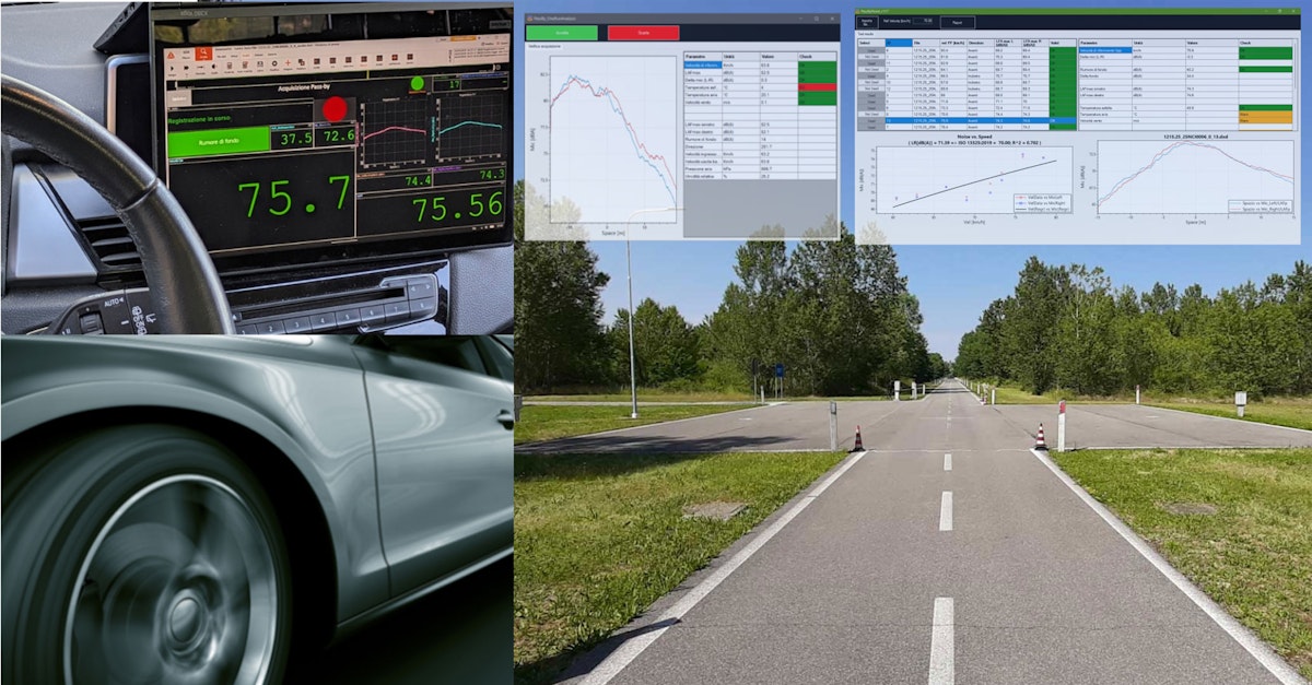
The measurement setup on the vehicle unit features a display working as a “main menu” GUI, where a few buttons linked to proper user input channels allow the sequencer to execute the required functions:
Initialization of the test session
Check the live data
Measure
Analyze
Exit
When the user presses a button, the sequencer switches to the intended measurement display, as will be explained later. The basic workflow is:
Initiate the test session: Enter the tires’ IDs and check or edit the track's bearing. The system needs this information to swap the signals between the left and the right microphones based on the driving direction.
Check the live data: ensure the ground station is transmitting the data and the weather station is working.
Go to measure: the following steps are executed in a loop until the driver decides to exit:
Arm the trigger and store the background noise
Drive through the measurement base
Automated post-processing of the test run, keep or discard the file
Analyze. At any time, usually at the end of the test session, the user may post-process the whole batch of files and make a report, or eventually check any individual test run.
Manage the post-processing and the test report
We went beyond DewesoftX at the customer’s request, though we would have preferred not to. The Dewesoft sequencer, among other things, allows calling an external application, so it was almost obvious to think of it. But which kind of external application? At the time of this project, we had been developing our GarageLab environment, which was ready to use and proved helpful for the job.
GarageLab consists basically of a runtime engine and a wrapper that gives access to processing and visualization libraries through python code: it allows a test engineer or an application specialist with basic coding skills to create automated data processing solutions hiding the complexity of low-level tasks such as loading a test file in a given format, managing channels, creating an interactive dashboard with nice widgets, exporting data. This simplification enables a more agile implementation and on-field debugging of data processing algorithms than developing a traditional executable application.
A simple prototype of a post-processing script allowed us to check the feasibility of the solution, so we decided to implement dedicated GarageLab Python scripts and to have them called by the sequencer when required by the automation workflow.
Implementation
The user interface and the measurement setup
Once we had sketched the architecture, we started developing a prototype of the User Interface, incorporating visual controls into the displays of the measurement setup. The sequencer and the measurement setup exchange information about the user interaction via control channels linked to the visual control widgets in the measurement display.
In this phase, we used just one computer and a simple simulation setup consisting of a few math channels, the Vehicle Simulation plugin, and the Polygon: this allowed us to simulate a vehicle running back and forth on the proving ground and going through the pass-by measurement base. So, by playing in this basic virtual environment, we were able to test user interactions and refine the UI and sequence design, saving a lot of time and money compared to working on a real test track with a real vehicle.
As a next step, we introduced a two PC simulated environment, setting the vehicle PC as a master MU connected via Ethernet to the ground PC set as a slave MU. One for the vehicle MU, one for the ground MU, at first via Ethernet, then introducing the Wi-Fi Kit. In doing so, we were able to focus on the setup rather than on Wi-Fi communication issues.
The processing scripts
In parallel, we refined the original post-processing Python script, which we developed in advance for a proof of concept. We adjusted the calculations and displayed output to match a detailed specification, including checks of environmental conditions, test execution, performance metrics, table data, and plots. On top of the processing module, we built a main script that handles selecting the test data file and displaying the aggregate results, a summary results table, a plot of noise vs. speed with curve fitting, and the option to view each test run.
The Sequencer allows us to integrate the processing tool into the measurement procedure seamlessly: from a block “Open file”, we execute the GarageLab runtime with additional parameters to specify the script to run and other relevant inputs, among which the path to the relevant dxd file(s).


The call to the GarageLab Python script is done by the Sequencer at different points in the workflow, with slightly different parameters:
In the PassBy procedure, automatically, at the end of each test run, immediately after the stop trigger, so the driver can check the validation conditions and decide to keep or discard the data file
In the Analyze procedure, it is accessible whenever the user wants to review a single test run or process the entire set of data files, inspect the results, evaluate the fit, and save a report to a custom template.
Putting everything together
The last step was to put everything together on a real car at our office to test the system in a more realistic setting before commissioning at the customer’s proving ground. Connecting the real sensors, adjusting math channels, setting the proper trigger conditions, and debugging the whole system takes a couple of days. Even if you have developed and tested everything, when you go to the proving ground, aside from the customer, there’s always something that still needs refinement or even debugging.
One of the main factors is the way the customer operates the system. If you are the person who develops the system, you know what you can and can’t do, and even if you identify some misuse cases, the customer will try doing something you hadn’t thought of.
The final solution
In the end, we were quite happy with the result. The main sequence looks simple and neat: after loading the measurement setup and setting the main display, it waits for the user to push one of the buttons in the measurement display, and then it routes the flow to the desired task:
Initialization of the test parameters
Checking live values from the sensors
Performing the pass-by test procedure
Analyzing the data
Exiting


The main menu design is a nice example of how effective the combination of the Sequencer and the user input control widgets can be for making an intuitive user interface for a simple test automation workflow in Dewesoft.
The “PassBy” procedure is the most important, as it is where we make the measurements.
Although the start of storage is triggered by a photocell a few meters before the vehicle enters the measurement base, the driver must collect background noise before starting each test run. The driver has to press the button to store the value. If driving over the reflector strip before doing this, no trigger action happens. After pressing the button, the driver must accelerate to the target speed and drive through the measurement base.


After the automatic stop storing, exiting the measurement base, the post-processing script displays a window showing the test results and a couple of buttons to keep or discard the test file.


The Sequencer waits until the driver has made a decision, and after that, the system is ready for another test run. The loop continues until the required number of test runs are complete, then the driver returns to the main menu and Analyze to run the “Global” analysis of the entire test session.


Data acquisition equipment list
DAQ hardware
Vehicle
Tablet PC (GETAC UX10)
LIGHT GATE (LEANE LI_LB1)
OPTRIS OPT CT LT15 CF CB3 - IR temperature sensor
Ground station
Laptop PC
2x GRAS-46AE - microphone
VAISALA WXT536 - weather station
GRAS-42AG - microphone calibrator
2x reflector strip (length 0.5 m each, fixed on the asphalt)
Software
Vehicle
DewesoftX (2021.x or later)
Remote link DEWESOFT-OPT-NET
Modbus client DEWESOFT-PLUGIN-MODBUS- CLIENT
Leane PBN software
GarageLab runtime GL v1.x
python scripts LI_PBN
Ground station
DewesoftX (2021.x or later)
Remote link DEWESOFT-OPT-NET
Acoustic analysis DEWESOFT-OPT-SNDLVL
Weather station plugin DEWESOFT-PLUGIN-NMEA-WS-NMEA
Measurements
We can’t show numeric results, e.g., a comparison of the current system with the previous one, or between different tires. Still, we can describe how a typical test session takes place to provide more insight.
When you arrive at the track, and you have to install the equipment in the booth, it takes about 30 minutes. It means to lay the Dewe-43 and the laptop on the desktop, hang the microphones on their supports at the measurement base, fix the reflector strips at the test track, fix the weather station and the Wi-Fi radio in place outside the booth, connect everything, power on, and start Dewesoft.
The setup of the test vehicle takes about the same time. You have to secure the tablet PC on its docking station in a convenient position, fix the GPS display, install the IR temperature sensor facing the asphalt, and finally, the toughest part on an HCV: put the GNSS antenna on the roof and the Wi-Fi radio at the highest possible location.
This setup is essential to ensure reliable communication (i.e., near-real-time data transfer) between the vehicle measurement unit and the ground measurement unit. Even when the system is perfectly tested and fine-tuned, the most common issues in everyday operation are related to the WiFi connection, due to increasing interference from radio waves.
After the microphone calibration, you can start the sequencer in the Vehicle Measurement Unit (master), which loads the pre-defined measurement setup, starts the measurement, and sets the main menu display; meanwhile, Dewesoft NET sends the measurement setup to the Ground Measurement Unit (slave). On the test vehicle, you navigate to the Initialization menu to enter the IDs of the tyre specs under test and to check the orientation of the test track: Dewesoft retains the last values of these parameters, so you can resume where you left off.
Now you can finally start.
A complete set of measurements on a single tire spec typically consists of 16 runs. They span the speed range between 60 and 80 kph (for HCV) to obtain a suitable curve and to interpolate the results at the target speed of 70 kph, according to R117 standard.
Collecting the 16 runs takes 15-20 minutes, depending on traffic, if the test track policy allows driving in both directions. If the PBN lane is one-way, the testing time may increase to 30-35 minutes. You have to arm the measurement at every run, paying attention to the traffic and the test speed. At the same time, the system detects the driving direction itself, handles swapping left/right mic data if needed, and presents the result right after stop-storing.
After that, you have to tap the Global analysis button to get the overall session results. You may select the test runs with the best correlation coefficient, review the individual test runs, remove outliers, and finally save the data to the template report.
Then you go back to the workshop where your team of mechanics fits another tire set.
At the end of a full testing day, you have tested up to eight tire specs, but it could be more than double if you could change the tires as they do in F1!
Key testing facts
| Fact | Value |
|---|---|
| Ground station setup time | 30 minutes |
| Vehicle setup time | 30 minutes |
| Number of runs for a tire set | 16 runs |
| Time to complete a full set | 15-20 minutes on the way and back track (30-35 on one-way) |
| Number of tire sets per day | 8 set/day (8 hours) |
Measurement results
In the end, the solution met all the customer's expectations, from the test driver to the test manager. Assuming the quality of the bare measurement data as given, the solution delivers a high overall testing efficiency, thanks to the following key achievements:
System cost
System portability
Ease of use
Automated processing of each test run
Integrated overall analysis and report
Three distinctive features of this solution are significant compared to other products on the market:
Fully customizable data processing and test report
One single person on the test vehicle can manage the whole test procedure
Digital transmission of the microphones’ data, avoiding further calibration (competitor systems rely on analogue data transmission)
Conclusion
The starting point of this project was a list of equipment, carefully selected based on customer requirements and the usual exchange between our Leane team and the Dewesoft team. At this point, we had the right measurement system, but had to turn it into the solution the customer demanded.
We felt the pressure of the challenge, but at the same time, we were quite excited because we had figured out how to combine the bricks to build the desired solution: the hardware, DewesoftX, the Sequencer, GarageLab, and the PBN scripts. We believe that what came out is just like any good design should be: simple and effective.
The commissioning of the first system took place in November 2021, at a proving ground in Northern Italy.
The solution has been used regularly since Spring 2022. After over a year and several test sessions at different proving grounds, a few minor issues had been identified and addressed in a new release with small changes to the Dewesoft setup and the PBN scripts in late 2023. We implemented new features for data processing and visual presentation in late 2024. In late 2025, the customer asked to supply a twin system for commissioning in a few weeks.