


On-Vehicle Magnetic Field Measurements in EVs, Beyond EMC Compliance
Francesco Lestini and Sara Amendola
Radio6ense
April 15, 2026
Electric vehicles already generate a rich magnetic signature as their powertrains operate, yet these signals are still mostly treated as compliance data and then ignored. Synchronized, multi-band on-vehicle measurements make it possible to turn electromagnetic “noise” into a powerful system-level observability tool during real-world driving. By capturing repeatable magnetic fingerprints of subsystems and drivetrain events, this approach opens new possibilities for predictive maintenance, hardware integrity verification, and deeper insight into EV behavior, even without access to internal vehicle data.
Introduction
Every electric vehicle already reveals what its powertrain is doing—engineers rarely listen. Magnetic field measurements are routinely performed for safety and regulatory compliance, then reduced to a pass–fail check and forgotten. As powertrains grow more complex and software-driven, this creates a critical observability gap during real-world driving, when many relevant behaviors occur, and internal signals may be unavailable or incomplete. This work shows how that gap can be closed by rethinking the acquisition and use of magnetic data.
Leveraging synchronized, multi-channel, and heterogeneous acquisition with Dewesoft instrumentation, magnetic emissions are captured as a coherent system-level signal rather than as isolated measurements. Through the DewesoftX environment, multi-band magnetic probes, vehicle kinematics, and positioning data are aligned in real time, enabling direct exploration and interpretation of magnetic signatures during on-road tests.
The results demonstrate that external magnetic fields contain structured, repeatable fingerprints of powertrain behavior. Auxiliary subsystems and drivetrain events, such as gear shifts, produce distinct signatures that remain observable without access to internal control data, revealing how energy flows through the vehicle. What engineers usually treat as electromagnetic noise becomes a reliable signal of powertrain truth.
Electric vehicles (EVs) are rapidly becoming a cornerstone of modern transportation, driven by stringent emissions regulations, advances in power electronics, and the global transition toward sustainable mobility [1]. In a modern EV, energy is routed and converted in real time by inverters, DC/DC stages, battery packs, and high-voltage cables. At the same time, one or more electric machines respond to torque requests that change every second.
These features are exactly what make EVs efficient and performant—but it also makes them harder to observe and understand while driving. In this context, magnetic fields are not an abstract side effect. They are a direct physical consequence of current paths and switching activity. Whenever power electronics commutate, whenever torque is built up or released, and whenever auxiliary loads engage, the current distribution changes—and magnetic emissions change with it (see Figure 1).
For years, the industry has measured these fields mainly for one purpose: safety and regulatory compliance, particularly for passenger exposure [1], [2], [3], [4] and potential interference with sensitive electronics and implantable medical devices [5], [6]. Many campaigns end with a binary outcome: compliant or not. The missed opportunity is that the same measurements can be much more than a checkbox.
If collected with the right method, magnetic field data can provide a non-invasive “window” into what the powertrain is doing, even when internal signals are unavailable, filtered, proprietary, or not recorded during on-road tests.
That window matters because many of the most valuable engineering questions show up outside the lab. Transient behaviors under load, subtle subsystem interactions, and short events that are easy to miss without the right tools.
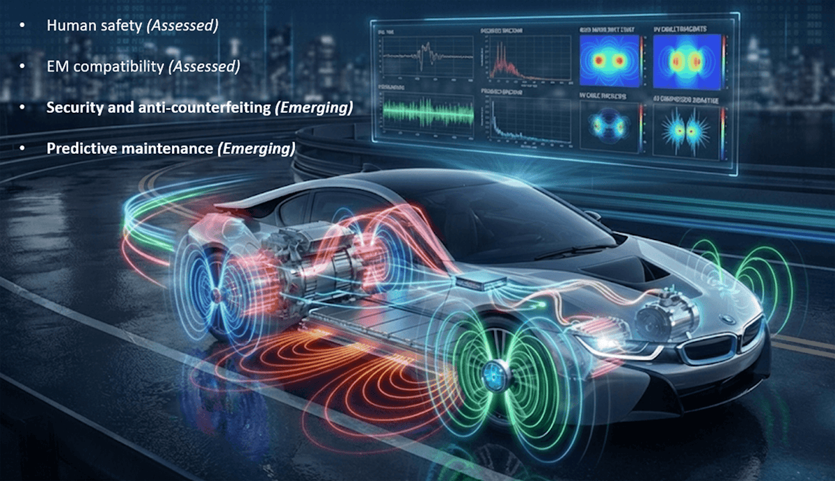
At the same time, two emerging challenges increasingly affect EVs:
1) Security and anti-counterfeiting
Battery packs, power electronics modules, and drivetrain components represent high-value assets that may be replaced, modified, or tampered with during the vehicle lifecycle [7]. Conventional electronic identification mechanisms can be bypassed, while software-based authentication depends on trusted internal reporting.
Magnetic emissions, on the other hand, originate directly from the hardware’s physical implementation and its operating behavior. Subtle differences in layout, switching dynamics, or current paths can produce distinctive and repeatable magnetic signatures, offering a potential physical fingerprint of critical subsystems.
2) Predictive maintenance
Similarly, changes in magnetic signatures can reveal emerging faults—such as motor imbalances, battery anomalies, or inverter misalignments—well before failures occur [8]. By turning these signatures into actionable indicators, magnetic diagnostics enable timely intervention, ultimately allowing EVs to anticipate failures rather than react to them.
Of course, turning magnetic emissions into engineering insight is not automatic. The EV environment is noisy and crowded, and what you measure depends strongly on where and how sensors are placed. Without synchronized acquisition and an analysis workflow that connects heterogeneous sources to vehicle operating conditions, the data remains difficult to interpret.
This work starts from that reality: the measurements already exist, the physics is information-rich, and the engineering value is there—but extracting it requires a practical, field-ready approach that can capture, align, and visualize magnetic emissions during real driving.
The problem: missing EM observability
Several engineering teams are involved in the development and operation of modern electric vehicles. Powertrain designers are responsible for validating electric machines, inverters, and high-voltage distribution systems under highly dynamic conditions. Vehicle testing groups perform extensive on-road campaigns to assess functional behavior, robustness, and efficiency before production.
At the same time, electromagnetic compatibility and safety engineers verify compliance with exposure regulations, while maintenance and reliability teams investigate abnormal behavior and early signs of component degradation once vehicles enter fleet testing or customer use. Although these stakeholders operate at different stages of the vehicle lifecycle, they share a common limitation: limited physical observability of what is happening inside the powertrain during real operation.
Today, most diagnostic and validation workflows rely on internal control signals, fault codes, and software-level monitoring. These tools are effective at detecting abrupt failures but are poorly suited to capturing slow degradation, partial faults, or subtle imbalances that develop over time. When these effects finally become visible, the cost is already high in terms of downtime, warranty claims, and root-cause investigation.
A similar limitation arises in the context of hardware integrity. Battery packs, power modules, and drivetrain components represent high-value assets that may be replaced, refurbished, or modified during maintenance or resale. From a functional perspective, a non-original component may still satisfy nominal electrical specifications, making its identification difficult using conventional diagnostics. Software identifiers and electronic serial numbers provide only partial protection because they rely on trusted internal reporting and can be altered or cloned.
What engineers are missing across development, validation, operation, and maintenance is a non-invasive, system-level observable that reflects the powertrain's physical reality: how currents are distributed, how switching behavior evolves, and whether a component's electromagnetic “fingerprint” still corresponds to its original condition.
This need is illustrated conceptually in Figure 1. In one case, an emerging fault within an electric machine produces an asymmetric spatial distribution of the magnetic field, revealing an uneven current flow that would be difficult to detect with conventional signals alone. In another case, a replaced or tampered component generates a magnetic signature that deviates from the original reference waveform, even though it appears electrically functional. In both situations, the system may continue to operate normally, yet its physical behavior has already changed measurably.
The core engineering challenge can therefore be summarized in a single practical question: how can engineers detect early physical deviations in the electric powertrain—caused by aging, faults, or hardware modifications—using non-invasive, reliable, and real-world-compatible measurements?
This work stems from the close collaboration between Radio6ense and the Electromagnetics Laboratory of the University of Rome “Tor Vergata”, from which Radio6ense originated as an academic spin-off. The proposed solution reflects a synergistic research-to-industry approach, where rigorous electromagnetic modeling and interpretation are directly translated into robust, field-ready measurement architectures.
This interplay enables the extraction of physically meaningful insights from complex
on-vehicle data, while maintaining the practicality required for real-world testing. While the need for non-invasive observability is clear at the system and lifecycle level, turning magnetic field measurements into a reliable diagnostic tool introduces a separate set of practical and physical challenges, which are addressed in the next section.

 Example of hardware tampering, showing the deviation of a magnetic emission signature from a nominal reference, revealing altered or non-authentic component behavior.")
Practical challenges of using magnetic fields as diagnostic signals
At first sight, using magnetic field measurements to assess system health or component authenticity may appear straightforward: currents flow, magnetic fields are generated, and sensors can detect them. In practice, however, the information of interest is deeply buried under several layers of complexity.
In a real EV, magnetic emissions originate simultaneously from multiple subsystems, including inverters, electric machines, high-voltage cabling, battery packs, and auxiliary electronics. The measured signal at any location is therefore a superposition of different sources, whose contributions overlap in both time and frequency. Relevant signatures related to degradation or hardware modifications are often subtle and easily masked by dominant components associated with normal operation.
Moreover, the spectral content of interest spans a wide range, from low-frequency components linked to current distribution to higher-frequency features associated with switching behavior and control dynamics. Capturing these phenomena requires multi-band sensing and sufficient temporal resolution, which go beyond typical compliance-oriented measurement setups. Spatial factors further complicate interpretation. Magnetic signatures depend strongly on sensor position and orientation, as well as on the physical layout of conductors and power electronics.
Without a coherent placement strategy and strict synchronization with vehicle operating parameters, it becomes difficult to associate observed patterns with specific subsystems or operating events.
For these reasons, magnetic field measurements, despite their physical richness, have remained largely confined to regulatory verification. Exploiting them as reliable indicators of degradation or hardware integrity requires a measurement architecture and analysis workflow specifically designed to isolate, align, and interpret subtle signatures under real driving conditions.
The solution
A first practical requirement quickly emerged from the problem itself: any viable solution had to integrate very different types of instruments within a single, coherent measurement framework. Multi-band magnetic probes, vehicle signals, and positioning data all needed to be acquired synchronously, managed consistently, and interpreted together.
Relying on separate acquisition systems or loosely synchronized devices would have introduced timing uncertainties, complex post-processing, and fragile experimental workflows—precisely the opposite of what is needed for reliable on-vehicle diagnostics and integrity assessment.
These requirements led to the adoption of the Dewesoft SIRIUS data acquisition platform, combined with the DewesoftX software environment, as the core of the proposed approach. From an engineering standpoint,
SIRIUS addressed the most critical constraint: synchronization of multiple heterogeneous channels. Its architecture allows all sensor inputs to be sampled as a single coherent system, preserving timing relationships even during fast transients such as load steps or drivetrain events. At the same time, the platform is designed for harsh environments, enabling stable operation inside the vehicle despite vibration, temperature variations, and strong electromagnetic interference.
However, reliable acquisition alone was not sufficient to close the observability gap. The decisive factor was the availability of an integrated software environment capable of transforming raw signals into interpretable information during the test itself. DewesoftX provided this missing layer by combining synchronized data acquisition with real-time visualization, time frequency analysis, and contextual vehicle information in a single interface.
This combination shifted the measurement process from passive recording to active exploration. Test scenarios could be adjusted on the fly, suspicious patterns could be investigated immediately, and reference conditions could be repeated and verified without waiting for offline processing. In practice, DewesoftX became not just a logging tool, but a working environment for understanding the electromagnetic behavior of the powertrain as it evolved in real time.
Data acquisition equipment
The measurements were conducted on a high-performance EV equipped with a dual-motor electric powertrain, comprising independent front- and rear-axle electric machines powered by a centrally located HV battery pack. This configuration provides a representative, sufficiently complex testbed for analyzing magnetic field emissions from multiple interacting subsystems.
Magnetic field sensing was carried out using a distributed set of uniaxial magnetic probes specifically designed for near-field magnetic measurements. The probe set covered three complementary frequency bands from 30 Hz to 1 MHz, enabling selective capture of electromagnetic phenomena associated with different physical mechanisms within the EV. In particular, the following probe models were employed:
MC910 probes (x4), optimized for low-frequency magnetic fields associated with quasi-static and low-frequency currents, such as those flowing in HV cables, battery interconnections, and auxiliary electrical subsystems. These probes provide a very strong response at 60 Hz and at lower frequencies.
MC95A probes (x4), designed to capture magnetic field components in the medium-frequency range (30 Hz-3 kHz), are typically used to characterize inverter switching harmonics, motor control dynamics, and current modulation effects.
MC165 probes (x4), intended for the detection of higher-frequency magnetic components related to fast switching transients, control edges, and rapid load variations. These probes operate over a very wide magnetic field frequency range: 2 - 300 kHz. From 300 kHz to 1 MHz, the output voltage response changes gradually and smoothly vs frequency.
A total of 12 magnetic probes were used in the experimental campaign, with four probes allocated to each frequency band. Each probe measures a single magnetic field component along its sensitive axis. This characteristic enables polarimetric analysis when probes are oriented in different spatial directions, allowing investigation of the directional dependence and source localization of magnetic field emissions.
The uniaxial configuration also facilitates physical interpretation of the measured signals by directly linking spectral features to current flow directions and subsystem locations.
Probe signals were routed to the SIRIUS Modular system using RG58 coaxial cables with BNC connectors. BNC female-to-female adapters were employed where necessary. All instrumentation components were powered by a vehicle-compatible DC power supply, enabling continuous operation during on-road tests without reliance on external power sources.
Finally, a GPS module was connected to the PC through a standard USB cable. The resulting instrumentation setup enabled synchronized, multi-band magnetic field acquisition across multiple vehicle areas under realistic driving conditions, forming a robust experimental basis for the spatial, spectral, and operational analyses presented in the following sections. Table 1 details the measurement instrumentation, and Figure 3 schematically illustrates the corresponding routing connections.
| Device | Description | Quantity |
|---|---|---|
| Dewesoft SIRIUS | Data acquisition system (DAQ) with 16 BNC channels | 1 |
| Magnetic Probe MC910 | Uniaxial magnetic field sensor operating around 60 Hz | 4 |
| Magnetic Probe MC95A | Uniaxial magnetic field sensor operating in the 30 Hz-3 kHz band | 4 |
| Magnetic Probe MC165 | Uniaxial magnetic sensor operating in the 2 kHz-1 MHz band | 4 |
| GPS Module | External module for vehicle tracking | 1 |
| Personal Computer (PC) | A laptop computer that allows interface with the DewesoftX software and a USB connection with a GPS module. | 1 |
| PC power supply | Universal notebook power supply for car (DC in / DC output) | 1 |
| BNC straight plug-plug RF coaxial cable 3m | RG58 Cables to extend the magnetic probe connections | 14 |
| BNC Adapter | BNC coaxial adapter Female/Female | 14 |


The measurement setup
The measurement setup was designed to capture both the spatial and polarimetric diversity of magnetic-field emissions from the EV powertrain and auxiliary subsystems under realistic operating conditions. Given the distributed nature of magnetic field sources within an EV, probe positioning was selected to enable correlation between measured signatures and specific subsystems while maintaining a non-invasive, repeatable configuration.
Magnetic probes were deployed in multiple vehicle areas of interest, including the front-end region, passenger cabin, and hood. These locations were selected to provide proximity to the main magnetic field sources—such as electric motors, inverters, and HV cabling—while also allowing assessment of magnetic field propagation toward passenger-accessible areas.
At each measurement location, probe orientation was carefully selected to investigate polarimetric diversity. Since the magnetic probes operate as uniaxial sensors, measurements were performed along different spatial axes (X, Y, and Z) depending on the test configuration.
The placement strategy also accounts for spatial diversity, allowing comparison of magnetic signatures acquired at different vehicle locations under identical driving conditions. This is particularly relevant for identifying localized phenomena, such as inverter-related switching components, motor-specific harmonics, or transient events associated with drivetrain operation.
Figure 4 illustrates the complete sensor placement strategy adopted during the experimental campaign, which highlights probe locations and the corresponding vehicle areas investigated.


DewesoftX software: dashboard and data visualization
To support both real-time monitoring during on-road acquisitions and consistent post-processing across multiple tests, a dedicated DewesoftX dashboard was developed (Figure 4). The dashboard provides a synchronized, multi-layer visualization of (i) probe-level magnetic measurements, (ii) vehicle operating conditions, and (iii) spatial context of probe placement.
This integrated view is essential for distributed sensing, as it enables rapid identification of events of interest (e.g., acceleration ramps, braking transients, mode transitions) and immediate verification of signal quality and channel coherence.


Test metadata and timeline control
The left portion of the dashboard includes a structured metadata panel reporting the active test configuration, including the investigated vehicle area, the selected probe axis, and the sequence of driving profiles executed during the run.
In addition, timestamps and elapsed-time indicators are displayed at the top of the interface, allowing the operator to continuously verify acquisition continuity and rapidly navigate the recording during offline inspection. A timeline cursor mechanism enables direct access to specific events and segments without manual trimming, thereby simplifying the selection of time windows for spectral analysis.
Spatial context: probe placement map
To the right of the metadata panel, a top-view schematic of the EV with color-coded markers representing probe positions is provided. This view maintains immediate awareness of the active sensing layout during each test, especially when multiple probe sets are distributed across different vehicle zones.
By visually linking channel identifiers to physical probe locations, the dashboard reduces ambiguity in interpreting spectral features. It facilitates comparisons among measurements acquired in different regions (e.g., front-end, cabin, and engine compartment).
GPS-based route tracking and kinematic indicators
To correlate magnetic emissions with operating conditions, the dashboard integrates GPS-based route tracking and kinematic indicators. A map panel displays the vehicle trajectory during the test, providing contextual information about road conditions and driving phases.
In addition, numeric indicators report key kinematic quantities such as velocity and longitudinal acceleration, which serve as high-level proxies for powertrain load conditions. These signals are used to segment the acquisition into well-defined operating modes (idle, cruising, acceleration, braking, etc.) and to interpret magnetic signatures in relation to the vehicle state.
Time–frequency monitoring: multi-channel STFT matrix
The right side of the dashboard is dedicated to magnetic field visualization through a matrix of short-time Fourier transform (STFT) spectrograms, one per probe channel. This arrangement enables immediate inspection of spectral content across the entire probe set, highlighting both persistent narrowband components (e.g., tonal harmonics) and transient broadband features (e.g., switching-related bursts).
Within the STFT matrix, each column corresponds to a single magnetic probe, while rows group probes operating in the same frequency band. The multi-panel structure is organized by sensing bandwidth, with probe channels arranged in ascending frequency order. Specifically, panels corresponding to the MC910 probes are shown first, followed by those associated with the MC95A probes, and finally by panels related to the MC165 probes.
The dashboard served two complementary purposes. During the acquisition, it enabled continuous verification of channel activity, signal integrity, and synchronization, ensuring that probe placement and routing choices did not introduce unexpected artifacts. During offline analysis, it provided an efficient navigation and segmentation tool, allowing specific driving phases to be isolated and compared across different vehicle areas and probe orientations.
The test results
We here present a focused subset of experimental results selected to illustrate how on-vehicle magnetic field measurements can be transformed from a compliance-oriented activity into a practical engineering tool. Rather than providing an exhaustive characterization of all recorded data, we intentionally limit the results to a small number of representative use cases.
The purpose of the examples is to demonstrate how non-invasive magnetic sensing can reveal operational states, dynamic events, and physically meaningful signatures that are directly relevant to predictive maintenance and hardware integrity assessment.
The examples should therefore be interpreted as proof-of-concept demonstrations. They show that, when appropriate reference conditions are available, you can use magnetic field measurements to infer the internal system behavior and to highlight deviations from expected patterns, even in the absence of direct access to internal control signals.
Magnetic field variations associated with auxiliary subsystem operation
Our first example focuses on magnetic field measurements taken in the front-end region, close to the inverter. We selected this location because power electronic operation, control strategies, and variations in electrical loading strongly influence magnetic emissions in this area.
Figure 6 compares representative magnetic field measurements recorded under idle conditions (i.e., the state in which the vehicle is stopped with the electric system active, but the electric motors are not in use), with the air-conditioning system alternately switched on and off. The figure reports representative spectrograms obtained from the three magnetic probes.

 and air-conditioning on (right) conditions. Results are shown for LF, MF, and HF probes, highlighting the emergence of distinct spectral components across multiple frequency bands when the auxiliary load is active.")
When the air-conditioning system is inactive, the magnetic spectrum is dominated by a 50 Hz component and its harmonics, which remain stable throughout the observation window. Aside from this low-frequency contribution, only a weak spectral component around 20 kHz is visible, attributable to baseline inverter switching activity.
When the air-conditioning system is activated, clear, repeatable changes occur across multiple frequency bands. In the low-frequency range, additional components appear, including a distinct contribution around 84 Hz. In the medium-frequency band, a pronounced spectral line appears at approximately 934 Hz, indicating a modification to the current modulation pattern associated with the auxiliary load.
In the higher-frequency band, structured spectral activity emerges, including a component around 40 kHz that is absent or strongly attenuated when the air-conditioning system is off.
The simultaneous appearance of these features across low-, medium-, and high-frequency probes highlights the inherently multi-band nature of magnetic signatures associated with auxiliary subsystem operation. Importantly, the observed differences are not limited to changes in amplitude but involve the emergence of distinct spectral components that can be directly linked to changes in inverter loading and control behavior.
Thus, from an engineering perspective, this result shows that auxiliary subsystems leave identifiable and repeatable magnetic fingerprints that can be monitored non-invasively. This demonstrates the feasibility of non-invasive monitoring of auxiliary subsystems, enabling early detection of abnormal load behavior without additional sensors or access to proprietary control data.
At the same time, the clear visibility of subsystem activity in externally measured magnetic emissions highlights their relevance as side-channel observables, capable of revealing internal operational states.
Detection of gear-shift events
The second example focuses on identifying gear-shift events associated with the rear electric motor, which is equipped with a two-speed transmission. Unlike the auxiliary load example, magnetic field measurements for this analysis were acquired in the rear region of the vehicle, near the second motor and its associated power electronics.
Figure 7 compares representative spectrograms obtained from the MC95A magnetic probes placed in the front-end and rear (hood) regions, respectively, under comparable driving conditions. In both cases, the spectrograms are shown alongside the corresponding vehicle speed profiles, allowing magnetic signatures to be directly correlated with acceleration and braking phases.


In the front-end measurements, the magnetic field evolution follows the overall acceleration and braking phases. Still, no distinct transient features associated with a gear-shift event are observed, even at high vehicle speeds. This behavior is consistent with the absence of a mechanical gear change in the front drivetrain, where torque delivery remains continuous. In contrast, the rear measurements show a clearly identifiable transient at approximately 113 km/h, corresponding to the rear drivetrain's gear-shift threshold.
This event manifests as an abrupt change in the spectral structure, producing a distinctive signature absent from the front-end measurements. The ability to discriminate between front- and rear-drive behavior highlights the spatial selectivity enabled by distributed magnetic sensing. Even though both drivetrains operate simultaneously, magnetic measurements acquired in different vehicle areas retain sufficient locality to isolate drivetrain-specific events.
This result demonstrates that externally measured magnetic fields can capture transient drivetrain events directly linked to mechanical and control actions within the powertrain. From a predictive maintenance perspective, we could monitor changes in the timing, spectral shape, or repeatability of such gear-shift signatures over time to detect wear, control drift, or mechanical degradation in multi-speed electric drivetrains.
From a hardware integrity standpoint, the presence and characteristics of these signatures also provide a potential fingerprint of drivetrain configuration, enabling the detection of altered or non-original components without accessing internal signals.
Conclusions
Engineers routinely collect magnetic field measurements in EVs for compliance and safety assessments, but their potential as an engineering signal is often left unexplored. This work shows that, when captured with appropriate bandwidth, spatial diversity, and synchronization, engineers can transform these measurements into a practical, non-invasive tool for understanding powertrain behavior during real-world driving.
The experimental results demonstrate that magnetic emissions carry structured, repeatable information directly linked to physical processes within the vehicle. Auxiliary subsystems generate identifiable multi-band signatures, while drivetrain events such as gear shifts produce localized transients that are detectable externally and correlate with operating conditions.
These signatures remain observable even without access to internal control signals, providing a complementary perspective to conventional diagnostics. From a practical standpoint, this enables new approaches to predictive maintenance and system monitoring. We can track changes in magnetic signatures over time to reveal evolving load conditions, abnormal behavior, or early signs of degradation, without modifying the vehicle.
At the same time, the physical origin of magnetic emissions makes them relevant for hardware integrity assessment, as deviations from reference signatures can indicate altered, non-original, or tampered components.
The proposed measurement framework, based on synchronized multi-band sensing and integrated visualization, proved effective in extracting meaningful insight from complex on-road data. Thus, what engineers traditionally treat as electromagnetic noise can instead become one of the most informative physical signals available for understanding, maintaining, and trusting future electric vehicles.
References
L. Tan, G. Li, Q. Xie, Y. Xiang, and B. Luo, “Study on the safety assessment and protection design of human exposure to low-frequency magnetic fields in electric vehicles,” Radiat. Prot. Dosimetry, vol. 200, no. 1, pp. 60–74, 2024.
A. Vassilev, A. Ferber, C. Wehrmann, O. Pinaud, M. Schilling, and A. R. Ruddle, “Magnetic field exposure assessment in electric vehicles,” IEEE Trans. Electromagn. Compat., vol. 57, no. 1, pp. 35–43, 2014.
P. M.-T. Concha, P. Velez, M. Lafoz, and J. R. Arribas, “Passenger exposure to magnetic fields due to the batteries of an electric vehicle,” IEEE Trans. Veh. Technol., vol. 65, no. 6, pp. 4564–4571, 2015.
ADAC, “E-cars: Health hazard from electrosmog?” [Online]
C. Lennerz et al., “High-power chargers for electric vehicles: are they safe for patients with pacemakers and defibrillators?” Europace, vol. 25, no. 5, May 2023, doi: 10.1093/europace/euad042.
C. Lennerz et al., “Electric cars and electromagnetic interference with cardiac implantable electronic devices: a cross-sectional evaluation,” Ann. Intern. Med., vol. 169, no. 5, pp. 350–352, 2018.
F. Marchiori and M. Conti, “Leaky batteries: A novel set of side-channel attacks on electric vehicles,” in International Conference on Availability, Reliability and Security, 2025, pp. 322–333.
Y. Wang, Y. Cheng, L. Ding, K. Yao, W. Li, and S. Cui, “Real-time Magnetic Field and Performance Prediction of EV Motors Based on Physics-Informed Machine Learning,” IEEE Transactions on Transportation Electrification, 2025.