


Bridge Structural Health Monitoring with Accelerometers and Modal Analysis
Giorgio Sforza
ESSEBI Srl
May 14, 2026
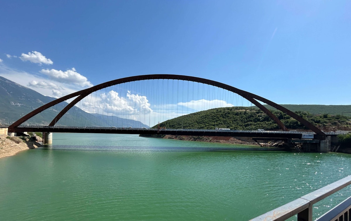
The Drinit Bridge in Kukës, Albania—one of the largest bow-string bridges in Europe—required advanced monitoring to ensure stability under strong lateral winds.
Using a network of Dewesoft MEMS triaxial accelerometers, optical strain sensors, and environmental transducers, engineers implemented a continuous structural health monitoring system. By applying advanced algorithms to derive displacement from acceleration data, the team verified safe dynamic behavior and avoided the need for costly tuned mass dampers.
Introduction
In the middle of 2024, the construction of a suspension bridge in Kukes, Albania, the largest in the Balkans, was completed. Its overall length is 300 m, and it consists of a forked arch with 47 hangers per side, supporting a deck made of two longitudinal beams with a concrete slab above. The deck, under tension, cancels out the arch's longitudinal thrust.


The bridge’s construction company, SALILLARI LTD, was established in Berat, Albania, in 1994. The engineering company is involved in several transport infrastructure projects financed by the Islamic Development Bank and the Albanian Government, including the Durrës-Rrogozhinë highway, the Qukës–Qafë Plloçë Road, the Tirana-Elbasan tunnel (Krrabe Tunnel), and others.
At the same time, we installed an impressive monitoring system comprising triaxial accelerometers, optical strands, temperature, and wind transducers. At the moment, the system is fully functional and measures kinematic and deformation parameters, enabling periodic modal analyses to assess the maintenance of the natural vibration frequency.
Considering that the preventive investigations in the wind tunnel have highlighted its strong vulnerability to excessive vertical displacements under medium-lateral actions, which are quite frequent on the site in question, we paid particular attention to this topic. In this sense, we have implemented ad hoc algorithms that allow the dynamic displacements to be obtained by double numerical integration and kept under control, starting from the measured accelerations.
The operation, apparently simple in principle, involved considerable computational effort due to the inevitable intrinsic noise of the instrumentation used and the very low frequencies involved. Laboratory tests allowed us to validate the quality and reliability of the adopted methodology, which ultimately allowed us to avoid the use of expensive tuned mass damping systems.
The challenge
On behalf of SALILLARI, ESSEBI Srl supplied and installed the structural monitoring system.
ESSEBI is an Italian engineering company specializing in structural diagnostics, dynamic testing, and structural health monitoring (SHM) of civil infrastructure and buildings. Founded in 1992 and headquartered in Rome, the company provides measurement-based engineering services to assess the safety, behavior, and long-term performance of structures.
The structural monitoring system, mainly dynamic, had to be in accordance with the specific requests deducible from the construction company. The purposes were:
A first dynamic characterization during testing before opening to determine the natural frequencies and the structural damping of the bridge. That is, to define a sort of dynamic, immutable identity card, which will remain the same until conditions arise that are capable of changing the configuration of the weights or, worse, the structural arrangement. These measurements will provide the required data to evaluate whether the damping is sufficient to ensure user comfort or to determine whether additional damping systems (TMDs) are required. For the installation of a TMD, the same monitoring system will provide measurements of the effectiveness of the additional damping system.
The structural behavior, in terms of stress-strain response, can be monitored at specific points using optical strands.
After the initial dynamic characterization of the bridge, the dynamic monitoring system will provide the recorded response to specific dynamic loadings, e.g., high-wind conditions, a seismic event, or an impulsive load.
Under normal conditions, the system will continuously provide acquisition and trigger storage to monitor the bridge's health over time.


The bridge structure
The bridge consists of three spans: the central one, measuring 270 m, and the other two at the ends, 20 m long (total length 310 m). At the top of the arch, it reaches a maximum height of 55 m. These dimensions make it one of the largest suspended-arch bridges in Europe.
At the extremities, it splits into two branches resting on concrete pillars, some of which were built directly in the water. The deck has a width of 23 meters, divided into two carriageways, each with two lanes in each direction. The structure is in weathering steel (Corten steel). It has been preassembled on the shore with the support of temporary towers and launched into position by means of a concrete barge, which, due to the large size required, was specifically built at the site.
The structure’s total weight is estimated to be 5000 tons. In the central portion, the arch consists of a stiffened box section measuring 2,9 m x 5 m, divided at the two ends into two square boxes measuring 2,9 m x 2,9 m that abut the four support constraints (two per end). Through openings near the supports, it is possible to access the inside of the boxes, which are fully inspectable, thanks also to special internal ladders.
The hangers are Full Locked Coil (FLC) ropes type with variable diameter, from 52 mm at the center of the span to 68 mm near the supports. The bowstring deck consists of two main double-T girders made up of a web welded to two flanges with a thickness of 29 cm, 4.5 m apart from each other. The collaborating reinforced concrete slab is connected to the upper surfaces of the two flanges of both girders via Nelson pegs.


The construction phases were finally developed in parallel with the executive project, as this is a critical aspect in a territory with very few areas suitable for pre-assembly. The construction phases were troubled by issues that were not at all technical in nature, and it is not appropriate to discuss them here. One after the other, the two most important Italian metalwork companies were involved: MAEG Costruzioni SpA performed the on-shore assembly, Cimolai SpA carried out the launching.
Monitoring system layout
We have installed the following transducers on the bridge:
N° 23 triaxial MEMS accelerometers, 23 triaxial MEMS accelerometers, six of which (four on the deck and two on the arch) are equipped with an external temperature sensor;
N° 4 optical strands in the mid-sections of the longitudinal deck beams;
N° 1 ultrasonic anemometer (with velocity and direction sensor).
The graphs in Figures 3 and 4 show their location on the plan and the relative wiring for connection to the central (digital cabling) and local (analog cabling) control panel.


For ease of representation, the plan is in two parts: a left one starting from the middle and running to the West shoulder towards Drini, and a right one starting from the middle and running to the East shoulder towards Kukes.


All the accelerometers on the intrados of the deck (n° 10) use a local orthogonal Cartesian reference in agreement with the global one reported in the figures above. Those placed inside the arch (n° 13) instead have their local x-axis coinciding, but with a discordant sign, with the global Z-axis. Applying the right-hand rule, the other two axes are determined: the local y-axis overlaps the global Y-axis with opposite sign, and the z-axis aligns perfectly with the global X-axis.
The three LAN dorsal lines consist of CAT 6 Ethernet cables with armored sheaths (mainly to counteract rodent activity). The Ethernet cables inside the arch are free and properly blocked to the walls with cable ties. Regarding the deck, the aforementioned cables were inserted into longitudinal ducts along the bridge slab, using corrugated pipes laid in place before casting. In this case, we appropriately interspersed the junction boxes.


CAT 6 Ethernet cables with armored sheaths, mainly to counteract rodent activity, constitute the three LAN lines. The Ethernet cables inside the arch are free and properly blocked to the walls with cable ties. Regarding the deck, the aforementioned cables were inserted into longitudinal ducts along the bridge slab, using corrugated pipes laid in place before builders cast the concrete. In this case, we appropriately interspersed the junction boxes.
The four optical strands (OS_1…OS_4) have been installed in the middle of the deck, in the intrados area, two on each side, precisely in correspondence with the internal parts of the upper and lower flanges, to measure the strain triangular diagram. As expressly indicated by the parent company, the optical strands, which are IP66-protected, have not been cased. The only precaution adopted was the insertion of an annular guide in their longitudinal centerline to avoid excessive flaking and, therefore, oscillating data due to wind action.
Measurement chain
The functional diagram of the monitoring system in Figure 7 shows the number and types of transducers. The architecture is star-shaped, with three daisy chains starting from a PC, each in a daisy-chain configuration.


From an industrial PC with the DewesoftX management software resident, housed in a special cabinet, three Ethernet lines depart via a six-port EtherCAT switch (one input from the PC and three outputs to the three chains of transducers), which, in addition to conveying the signal, also provides power.
Compliant with IEEE 802.3af and 802.3at standards, PoE (Power over Ethernet) devices provide power by connecting to the external electrical network. We positioned them at the beginning of each of the three lines, and based on. These allow the signal cables to serve dual roles, i.e., to also provide power to the measurement elements arranged in cascade. Given the number of modules per line (7 to 9) and the spacing between them, it was possible to use a single PoE port for each module, all housed inside the panel that houses the PC.
Rather than transducers, it makes sense to talk about accelerometer modules, due to the devices that make up the chain. In addition to the sensitive element for measuring the quantity of interest, the transducers, Dewesoft IOLITEi3xMEMS, have all the electronics for conditioning, amplification, A/D conversion, and, above all, signal synchronization on board.
Between the first and the third accelerometric module of line 1, always with an enter-exit architecture to reproduce what happens for the modules themselves, a 16-channel data acquisition system (DEWESoft IOLITE 16x) is inserted, which refers to six analog transducers (4 optical strands and an ultrasonic anemometer with its two channels, one for speed and the other for direction).
Test results
The 23 installed accelerometers, in addition to enabling continuous monitoring of maximum acceleration amplitudes, also enable periodic operational modal analyses (OMA) [1] to assess the stability of the dynamic parameters and verify the general state of health of the structure (SHM). Using the PolyMAX algorithm, operating in the frequency domain and available in the Siemens TestLab software [2], over 25 well-defined and distinct modal shapes were identified in the range from 0.5 to 2.5 Hz. The first flexural mode is shown below, with its inversion of curvature on the deck, due to the particular architectural configuration.


The four optical strings in the middle of the deck allow continuous measurement of the seasonal thermal deformation, as well as that due to vehicle traffic or wind conditions.
The two optical strands placed at the intrados show a thicker curve, due to the stresses deriving from the very frequent transits, as they are further from the neutral axis [3]. The other two feel the transits very little and show the deformation trend due to the temperature, superimposed on the temperature trend itself (secondary ordinate).
We also implemented numerical integration algorithms to determine the displacements induced by lateral wind [4] and to compare them with the decidedly alarmist results from previous wind-tunnel tests (CRIACIV in Prato, near Florence). The maximum vertical displacements measured in correspondence with lateral winds with speeds of even more than 20 m/s were always within values not exceeding 2 cm.


Conclusions
At present, the Drinit bridge in Kukes has a continuously operating monitoring system that acquires and stores acceleration values at 23 instrumented points and deformations at 4 points in the middle of the deck, along with wind speed and direction measurements.
The various operational modal analyses performed have made it possible to verify the perfect correspondence of the modal parameters with those deriving from the FEM analysis supplied to us by the structural designer, and above all, their immutability over time. The optical strands provide extremely consistent deformation variability of the deck, which is compliant with the day-night and seasonal thermal expansions of the deck.
Above all, continuously measuring the deck’s vertical displacements, verifying that they remained within a centimeter, and preventing aeroelastic criticalities allowed engineers to avoid the use of very expensive tuned mass damping (TMD) systems, which wind-tunnel model tests had suggested were almost certainly necessary.
References
Ewins, D.J.: Modal Testing. References Studies Press LTD. Baldock, Hertfordshire, England, 2000.
Heylen, W., Lammens, S., Sas, P.W., White, E.B.: Modal Analysis Theory and Testing. Katholieke Universiteit Leuven - Departement Werktuigkunde; 2003.
Hoffman, K.: An Introduction to Measurements using Strain Gages. Hottinger Baldwin Messtechnik GmbH Darmstadt; 1987.
Prandtl L, Tietjens O.G.: Applied Hydro and Aeromechanics. Dover Publications Inc., New York, 1934.