Innehållsförteckning
Bläddra bland kategorierna
Bläddra bland författare
 AB
ABAlberto Boffi
 AL
ALAlessia Longo
 AH
AHAl Hoge
 AB
ABAljaž Blažun
 BJ
BJBernard Jerman
 BČ
BČBojan Čontala
 CF
CFCarsten Frederiksen
 CS
CSCarsten Stjernfelt
 DC
DCDaniel Colmenares
 DF
DFDino Florjančič
 EB
EBEmanuele Burgognoni
 EK
EKEva Kalšek
 FB
FBFranck Beranger
 GR
GRGabriele Ribichini
Glacier Chen
 GS
GSGrant Maloy Smith
 HB
HBHelmut Behmüller
 IB
IBIza Burnik
 JO
JOJaka Ogorevc
 JR
JRJake Rosenthal
 JS
JSJernej Sirk
 JM
JMJohn Miller
 KM
KMKarla Yera Morales
 KD
KDKayla Day
 KS
KSKonrad Schweiger
Leslie Wang
 LS
LSLoïc Siret
 LJ
LJLuka Jerman
 MB
MBMarco Behmer
 MR
MRMarco Ribichini
 ML
MLMatic Lebar
 MS
MSMatjaž Strniša
 ME
MEMatthew Engquist
 ME
MEMichael Elmerick
 NP
NPNicolas Phan
 OM
OMOwen Maginity
 PF
PFPatrick Fu
 PR
PRPrimož Rome
 RM
RMRok Mesar
 RS
RSRupert Schwarz
 SA
SASamuele Ardizio
 SK
SKSimon Kodrič
 SG
SGSøren Linnet Gjelstrup
 TH
THThorsten Hartleb
 TV
TVTirin Varghese
 UK
UKUrban Kuhar
Valentino Pagliara
 VS
VSVid Selič
 WK
WKWill Kooiker
Modal Test on Hydro Turbine Buckets

TIWAG, a major Austrian power plant operator, asked for assistance to validate a redesigned water turbine. The old model broke due to a resonance overlap of the shaft speed and self-resonance of the buckets. Dewesoft provided an effective field solution for quick validation of turbine modal parameters - and to save the data for evidence in case of future trouble.

TIWAG is the leading energy service provider in the western Austrian Alp region, Tyrol. The company installs and maintains hydroelectric power stations. In addition to hydropower, it also generates environmentally friendly electricity from domestic, renewable energy sources, such as photovoltaics and biomass.
The issue
This big Austrian power plant operator asked for our assistance to validate a redesigned hydro turbine model, which was currently in service at another company specializing in turbine manufacturing.
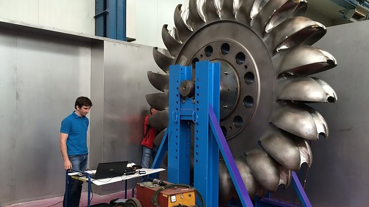
The redesigned turbine is a Pelton model - a fairly simple design. A large circular disk mounted on a rotating shaft known as a rotor. On the disk are cup-shaped blades known as buckets evenly spaced around the entire wheel. Nozzles then introduce water jets on the buckets and make the turbine spin.
In this case, the disk has a diameter of approximately 4 meters and weighs 10 tons. It has 23 spoon-shaped buckets, driven by six water nozzles with around 120 bar, runs at a nominal speed of 500 rpm, and generates a power of 250 MW.
The design had to be improved. The previous model broke due to an unexpected resonance overlap of a higher harmonic of the shaft speed and the self-resonance frequency of the buckets. The result was heavy vibrations causing the total turbine loss.
The engineers at TIWAG needed a solution to validate the modal characteristics of the new turbine design with a modified bucket shape. The altered bucket shape should shift the vibration pattern in the first mode from 700 Hz up to around 770 Hz, which the engineers considered safe.
Dewesoft offered an effective field solution for validating the modal testing and analysis of the turbine bucket design - and saving the data for evidence in case of future trouble.
Solution setup
Hardware
Dewesoft SIRIUSi custom with 2xACC, 2xACC+, 2xHV, 2xMULTI - 8-channel isolated data acquisition system with USB2 interface
Endevco 2302-100 (scaling: 22,7 mV/N) - modal hammer
PCB 352A56 (scaling: 99,3 mV/g) - acceleration sensor
Software
DewesoftX - test and measurement data acquisition software for data recording, signal processing, and data visualization
DewesoftX-DSA - software package including modal test option, OPT-MODAL-TEST.
Modal testing
In this case, we considered tap testing or experimental modal testing the proper way of testing. This method has the advantage that it only requires a minimum of equipment - only one roving or impact hammer and one sensor are needed.
After a test hammer hit, it turned out that the natural frequencies of the 23 rotor buckets were around 770 Hz. Due to the manufacturing precision of the turbine, they were lying very close to each other, and the phase turned multiple times in a narrow frequency range.
The selection of the sampling rate (5000 Hz) and line resolution (8192 lines, df = 0.305 Hz) was the most critical. We needed to match both settings while also keeping an eye on the resulting measurement time of each hit. It shouldn’t be too long.
The applied frequency resolution required acquiring a rather large amount of data and a relatively long measurement time to calculate one FFT (t = 1 / df = 1 / 0,305 Hz = 3,28 sec). As the massive steel structure has low damping, the ringing tone after each hammer tap lasted for quite a few seconds before fading out. So, leaving enough time between the hammer hits was also important.
The geometry model
In the software’s Modal Geometry Editor, we simplified the bucket to a 2D shape with eight hit points aligned on the upper edge. For proper visualization and shading of the movement, we connected these dots by lines, using a few three-point shapes in between.
The accelerometer was mounted in point no. 8 while we moved the hammer taps through points 1 to 8. We did three hammer taps at each measurement point to obtain a valid average result. And for each bucket, we created a new data file.
Measurement screen
The display in figure 6 is auto-generated by default immediately when the measurement starts. The measurement screen allows online validation of the excitation and response signals in the time- and frequency-domain - to quickly identify double hits and repeat and to see the transfer function and coherence.
The software marks the currently measured point in red. The geometry is rotatable in 3D with the mouse, and multiple visualization options, such as top, side, orthogonal view, and undeformed background shape, are available.
Modal analysis
Measurements completed, we switched to the predefined “Modal test - Analysis” screen to study all the transfer functions - the amplitudes and the phases in a Bode plot. When the phase is turning 180 degrees and the amplitude is at max, this indicates a resonance.
Frequency and damping
The spectrum showed a lot of resonances in a narrow band - in figure 7, we have zoomed in from 750 to 800 Hz. At this time, we were mainly interested in our first mode at around 780 Hz. In this case, the linear y-axis scaling is easier for finding the dominant peak.
The modal circle provided the option to have more accurate results from our experimental modal test. It interpolates between the FFT lines. The structure animation below nicely shows the first mode shape - up/down movement of the bucket and undeformed structure in light-gray color. Notice the low damping factor due to the massive steel structure.
Conclusion
The measurement on all 23 buckets showed an average resonance frequency of 782,5 ± 3,9 Hz. The TIWAG engineers evaluated this as acceptable - the new turbine design to be operationally safe. The complete measurement process, including making the setup, lasted only around 2 hours, and TIWAG is looking forward to using this simple solution in daily business.
“Our vehicle trunk was always stocked up with equipment and cables when using the previous measurement system,” the head of the TIWAG testing department states. “The Dewesoft system is a much more compact and robust solution. And we now finish testing in a shorter time - and with lots of pleasure!”